Core biopsy device

Inactive Publication Date: 2006-02-09
INRAD
View PDF82 Cites 118 Cited by
  • Summary
  • Abstract
  • Description
  • Claims
  • Application Information

AI Technical Summary

Benefits of technology

[0025] The invention also relates to a method of conducting a percutaneous biopsy by removing a core specimen from a predetermined site in a tissue mass, wherein the specimen core is supported by the biopsy device for easy removal by the practitioner. The method comprises: advancing an open-tipped cannula defining a lumen into the predetermined site in the tissue mass to at least partially form a specimen core containing at least a portion of the tissue

Problems solved by technology

The disadvantage of this method is that it produces a small core biopsy relative to the outer cannula size since the cross section of the sample is substantially equal to the cross section of the stylet notch, which is substantially smaller than the cross section of the outer cannula.
The disadvantage of this full core device is that the end of the sample is not positively severed from the tissue mass, creating the possibility that the biopsy sample will be pulled out of the coring cannula upon the withdrawal of the coring cannula.
This can happen if the forces holding the sample in the coring cannula are not sufficient to tear the end of the sample from the tissue mass.
However, if these forces are not sufficient to tear the end of the sample from the tissue mass, the sample will be pulled out of the coring cannula upon the removal of the coring cannula.
However, this is not preferred as it increases the damage to the remaining tissue.
A disadvantage of this method is that the sample is not truly a full core sample since part of the interior of the cannula was reserved for the raceway.
If the sample produced by the cannula with the raceway was the same size as the full core sample, the cannula with th

Method used


Image

  • Core biopsy device
  • Core biopsy device
  • Core biopsy device

Examples


second embodiment

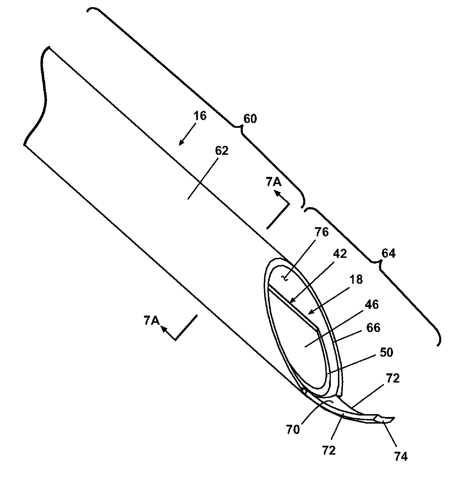
[0121]FIG. 10 illustrates the spoon cannula 18 in which the spoon section 42 is provided with an excising finger window 80 adjacent the insertion tip 48. The excising finger window 80 is a generally rectilinear opening in the arcuate wall 46 comprising a pair of parallel, spaced-apart longitudinal edges 82 defining a window width 84 adapted for slidable insertion of the excising finger 70. The excising finger window 80 has a distal edge 86 adjacent the insertion tip 48. The spoon cannula 18 is received as previously described in the lumen 76 for slidable movement of the spoon cannula 18 relative to the coring cannula 16.

first embodiment

[0122] The excising finger 70 is adapted for insertion through the excising finger window 80 so that the excising finger 70 bears against the distal edge 86. As the spoon cannula 18 is drawn into the coring cannula 16, the distal edge 86 bearing against the excising finger 70 will urge the excising finger 70 radially inwardly toward the longitudinal axis 76. Conversely, as the spoon cannula 18 is moved distally along the lumen 76, the finger 70 will resiliently return to its at-rest position. Because the distal edge 86 deflects the excising finger 70, the curvature of the excising finger 70 in its at-rest position can be much shallower, even approaching a straight line, thereby facilitating penetration of the excising finger 70 into the tissue 22 and the lesion 24. With a shallower curvature, the excising finger 70 will be less likely to deflect laterally during penetration. The deflection of the excising finger 70 by the movement of the spoon cannula 18 will enable the excising fin...


PUM


Abstract

A core biopsy device comprises an outer cutting cannula in telescoping register with an inner spoon cannula. The outer cutting cannula is provided at a distal end with an arcuate excising blade that is biased radially inwardly to extend beyond the longitudinal axis of the cannula. The inner spoon cannula terminates at a distal end in an arcuate wall to form a biopsy sample spoon for supporting a biopsy sample thereon. The outer cutting cannula can be rotated relative to the inner spoon cannula so that the excising blade can excise the biopsy sample from the surrounding tissue. After removal of the core biopsy device from the tissue, the outer cutting cannula can be retracted away from the inner spoon cannula to reveal the biopsy sample and enable the sample to be removed from the biopsy device in a relatively undisturbed condition.

Description

CROSS-REFERENCE TO RELATED APPLICATION [0001] This application claims the benefit of U.S. provisional application Ser. No. 60 / 521,518, filed May 11, 2004, which is incorporated herein in its entirety.FIELD OF THE INVENTION [0002] The invention relates to a core biopsy device for obtaining biopsy samples from tissue, and more particularly, to a core biopsy device having a rotatable excising finger for separating the core biopsy sample from the tissue. DESCRIPTION OF THE RELATED ART [0003] It is frequently necessary to sample or remove a sample from a suspect tissue for testing. In humans, such a sample removal is particularly useful in the diagnosis and treatment of cancerous or pre-cancerous conditions. In the case of suspected cancer, particularly cancer of the breast, early detection and diagnosis is critical to the success of the patient's treatment and recovery. [0004] Various techniques are available to aid in detection and diagnosis, including physical examination and imaging,...

Claims


Application Information

Patent Timeline
IPC IPC(8): A61B10/00A61B10/02A61B10/04A61B17/32
CPCA61B2017/32004A61B10/02A61B10/0233A61B10/0266A61B2010/045A61B10/04A61B17/32053A61B2010/0208A61B2010/0225A61B10/0275
Inventor FIELD, STEVEN E.MULDER, BRIAN R.JOHNSON, MICHAELIRELAND, TODDHAESKE, STEVEVANDER VEEN, MARK
Owner INRAD
Why Eureka
Try Eureka