Methods and apparatus for pinplasty bone resection

a pinplasty and bone resection technology, applied in the field of methods and bone resection equipment, can solve the problems of inability to support the saw blade, simply not possible, and the distance or cutting end of the saw blade is not supported by the guide, so as to reduce the dependency of planar saw cuts and reduce implant placement errors

Inactive Publication Date: 2006-02-09
BIOMET MFG CORP
View PDF99 Cites 272 Cited by
  • Summary
  • Abstract
  • Description
  • Claims
  • Application Information

AI Technical Summary

Benefits of technology

[0013] In one embodiment for a cutting tool having a generally linear cutting profile, the present invention utilizes a plurality of pin members located within at a series of independent pin apertures where a tangential surface of the pin cooperates with a flat surface of a planar saw blade to act as a cutting guide internal to the bone. Two or more of these tangential surfaces form corresponding lines of contact on the intended plane of a resected surface to be created by the linear cutting profile of a planar saw blade. The location and orientation of the pin members serve to define the intended plane of the resected surface. It will be seen that the location and orientation of the pin members, together with the orientation and operation of the planar saw blade, permit the tangential surface of the pin members to effectively guide not only the proximal end of the planar saw blade, but also distal portions of the planar saw blade. Depending upon the operation and orientation of the planar saw blade, at least two points or portions of the lines of contact with the flat surface of the planar saw blade are preferably maintained during operation of the planar saw blade. By maintaining at least two points or portions of contact, the pinplasty technique of the present invention overcomes the tendency of the planar saw blade to deflect or curve while cutting bone when guided only from the proximal end.
[0014] It is an often repeated rule of thumb for orthopedic surgeons that a “Well placed, but poorly designed implant will perform well clinically, while a poorly placed, well designed implant will perform poorly clinically.” The present invention provides a method and apparatus for reducing implant placement errors in order to create more reproducible, consistently excellent clinical results in a manner that decreases the dependency of planar saw cuts on the level of manual skill of the surgeon creating a resected surface.

Problems solved by technology

One of the critical problems with existing cutting guide systems for planar saw blades is that the distal or cutting end of the saw blade is not supported by the guide as the saw blade cuts through bone.
Because the distal end includes the cutting profile of the planar saw blade, it is simply not possible with conventional guide systems that are located exterior to the bone being cut to positively guide the distal end of the planar saw blade.

Method used


Image

  • Methods and apparatus for pinplasty bone resection
  • Methods and apparatus for pinplasty bone resection
  • Methods and apparatus for pinplasty bone resection

Examples


Embodiment Construction

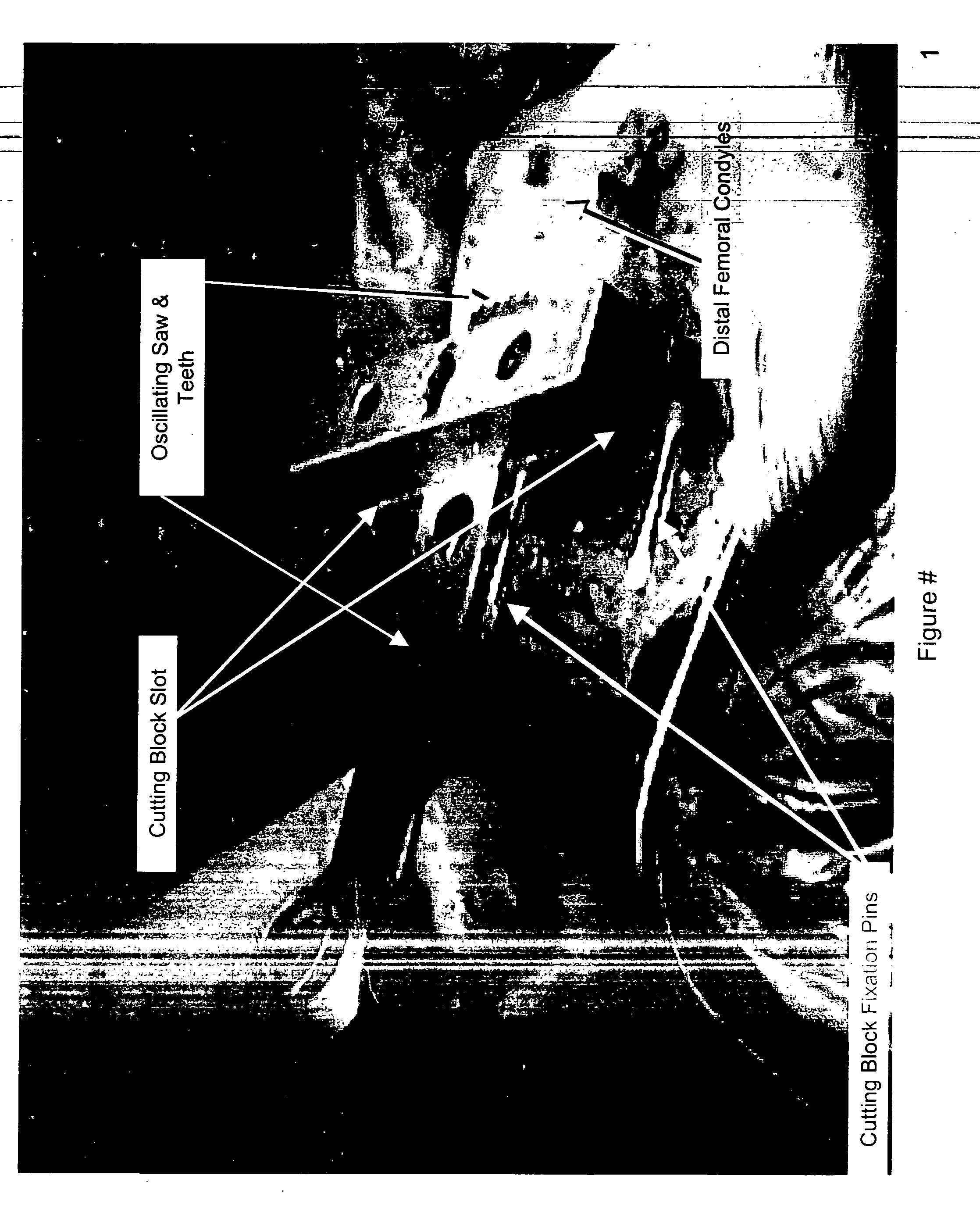
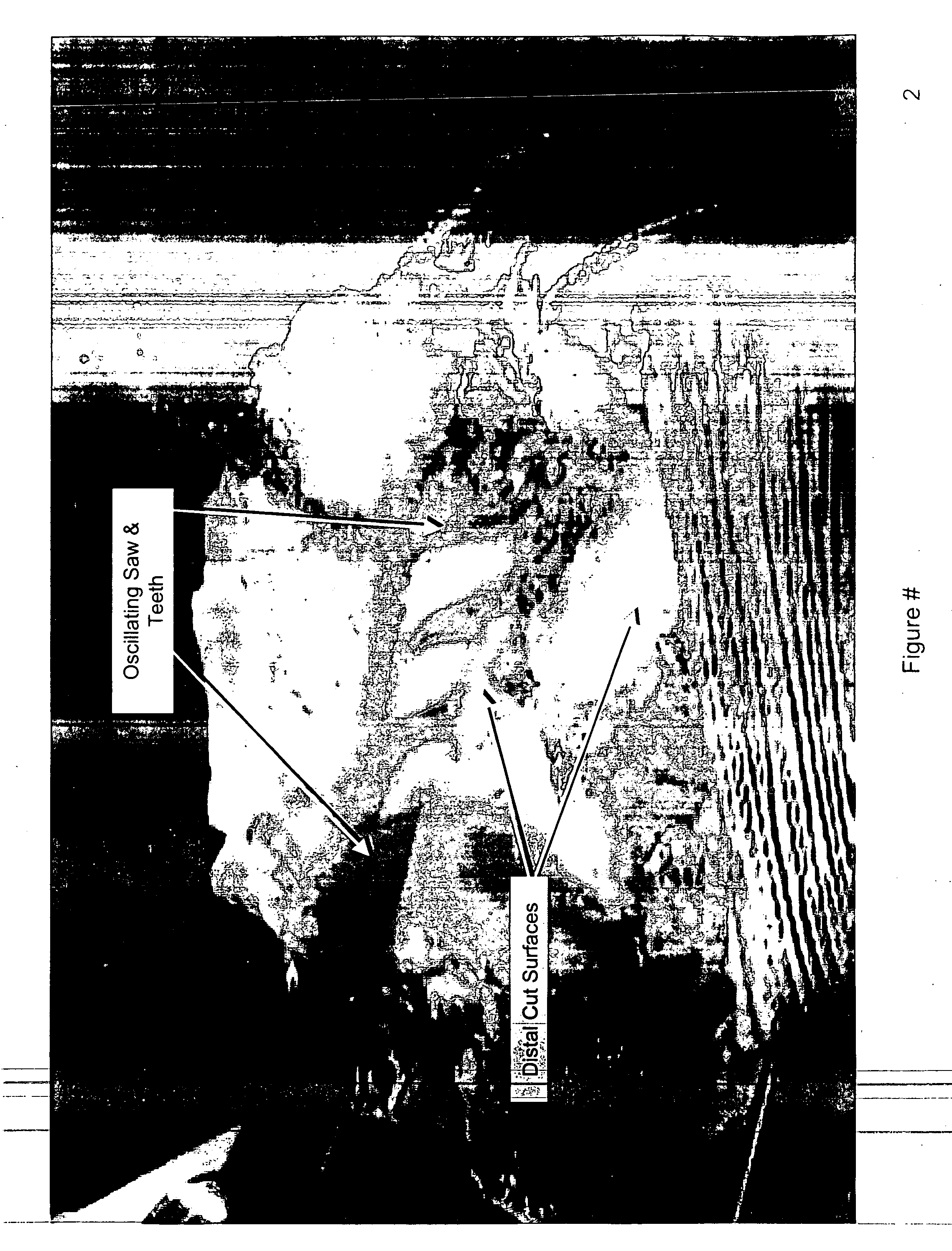
[0019]FIGS. 1 and 2 show a conventional oscillating saw blade system in action. The basic components are the oscillating saw, the cutting guide, and fixation features of the cutting guide, which in this case are 0.125 inch drill pins. The cutting guide possesses at least one slot to which the saw is engaged during cutting. A drawback about this technology is shown in FIG. 2 as the saw blade is in an extended cantilever as it finishes the side of the cut furthest from the guide generating sometimes significant error requiring recutting or tweaking of the cut by eye as shown in FIG. 2.

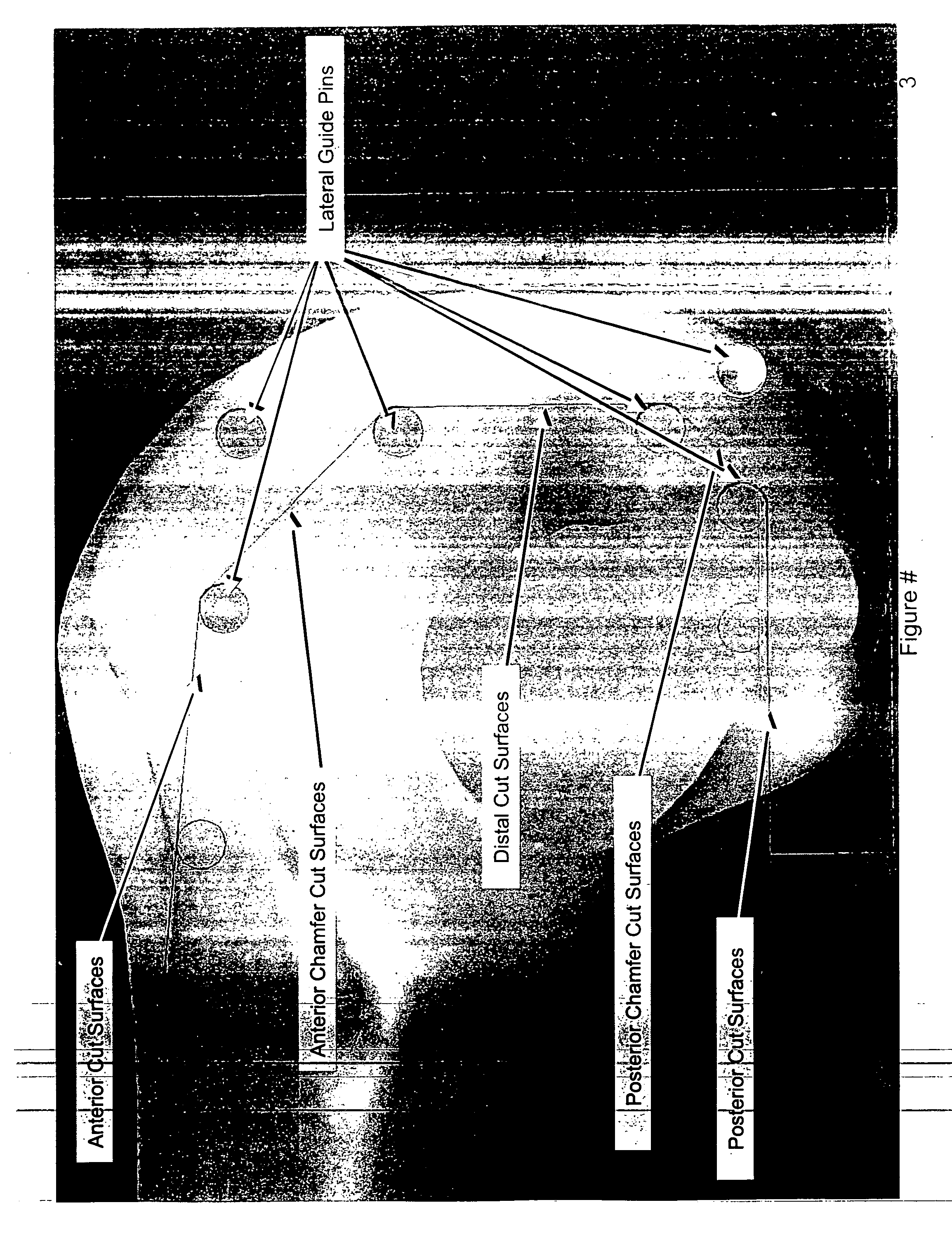
[0020]FIGS. 3-49 show various depictions of the placement of pin members in accordance with one embodiment of the present invention. FIG. 3 is a view from medial to lateral showing the intended location of the cuts and some of the possible pin locations. In this particular form of this concept, the ‘guide’ is merely a series of independent pins positioned through, at, above, or below the cut surfaces to...


PUM


Abstract

Methods and apparatus for performing arthoplasty utilizes a plurality of apertures created in a bone, each aperture having a cross section defined perpendicular to an axis of the aperture that intersects a plane of a resected surface to be created in the bone and also intersects a peripheral rim border that externally delineates the resected surface. A pin feature is inserted into each of the plurality of apertures and the resected surface is created by guiding a cutting tool along at least a line of contact of the pin features. An implant can then be attached to the resected surface.

Description

RELATED APPLICATIONS [0001] The present invention claims priority to U.S. Provisional Application No. 60 / 536,320, filed Jan. 14, 2004; U.S. Provisional Application No. 60 / 540,992, filed Feb. 3, 2004; U.S. Provisional Application No. 60 / 551,080, filed Mar. 8, 2004; U.S. Provisional Application No. 60 / 551,078, filed Mar. 8, 2004; U.S. Provisional Application No. 60 / 551,096, filed Mar. 8, 2004; U.S. Provisional Application No. 60 / 551,631, filed Mar. 8, 2004; U.S. Provisional Application No. 60 / 551,307, filed Mar. 8, 2004; U.S. Provisional Application No. 60 / 551,262, filed Mar. 8, 2004; and U.S. Provisional Application No. 60 / 551,160, filed Mar. 8, 2004, the disclosures of which are hereby fully incorporated by reference.BACKGROUND OF THE INVENTION [0002] 1. Field of the Invention [0003] This invention generally relates to methods and apparatus for bone resection to allow for the interconnection or attachment of various prosthetic devices. More particularly, the present invention relate...

Claims


Application Information

Patent Timeline
Patent Type & Authority Applications(United States)
IPC IPC(8): A61B17/16
CPCA61B17/15A61B17/157A61B17/155
Inventor HAINES, TIMOTHY G.
Owner BIOMET MFG CORP
Why Eureka
Try Eureka