Distributed input/output control systems and methods

a control system and input/output technology, applied in the direction of electric controllers, program control, electric programme control, etc., can solve the problems of increasing manufacturing costs, large, bulky and complex wiring harnesses, and conventional systems, and achieve the effect of high cost effectiveness

Inactive Publication Date: 2006-02-09
EI ELECTRONICS
View PDF10 Cites 56 Cited by
  • Summary
  • Abstract
  • Description
  • Claims
  • Application Information

AI Technical Summary

Benefits of technology

[0007] In accordance with the present invention, a large number of inputs and outputs may be provided in the equipment, line or environment, with distributed I / O modules communicating with the main controller over a suitable bus, as opposed to a bulky wiring harness, etc. Redundant controllers in the main controller and the I / O modules, in accordance with preferred embodiments of the present invention, provide redundant, programmable, interlock control for the equipment, line or environment, etc. Standard-type I / O modules enable technicians to more readily repair and upgrade the equipment and the like.
[0010] Finally, it is an object of the present invention to provide such control systems and methods that utilize a main controller and distributed I / O modules having redundant processors in order to provide redundant interlock control in a distributed, programmable and highly cost effective manner.

Problems solved by technology

While the advances in this general field have been relatively great, due to reasons such as safety and conventional design practices, there are a number of undesirable attributes of such conventional control systems.
Such conventional systems, while providing a highly centralized form of control, suffer from various disadvantages.
For example, the numerous wires that must pass from cards 14 to the various relays often result in large, bulky and complex wiring harnesses.
Bulky and / or complex wiring harnesses, for example, increase manufacturing costs, make changes in the system more difficult, and can result in undesirable compromises in the overall system physical design in order to accommodate the wiring harnesses.
In addition, it is often more difficult to implement redundancy with such a centralized control system, and the problems associated with maintenance and / or upgrades to the equipment tend to be complex and difficult.

Method used


Image

  • Distributed input/output control systems and methods
  • Distributed input/output control systems and methods
  • Distributed input/output control systems and methods

Examples


Embodiment Construction

[0020] The present invention will be described in greater detail with reference to certain preferred embodiments and certain other embodiments, which may serve to further the understanding of preferred embodiments of the present invention. As described elsewhere herein, various refinements and substitutions of the various embodiments are possible based on the principles and teachings herein.

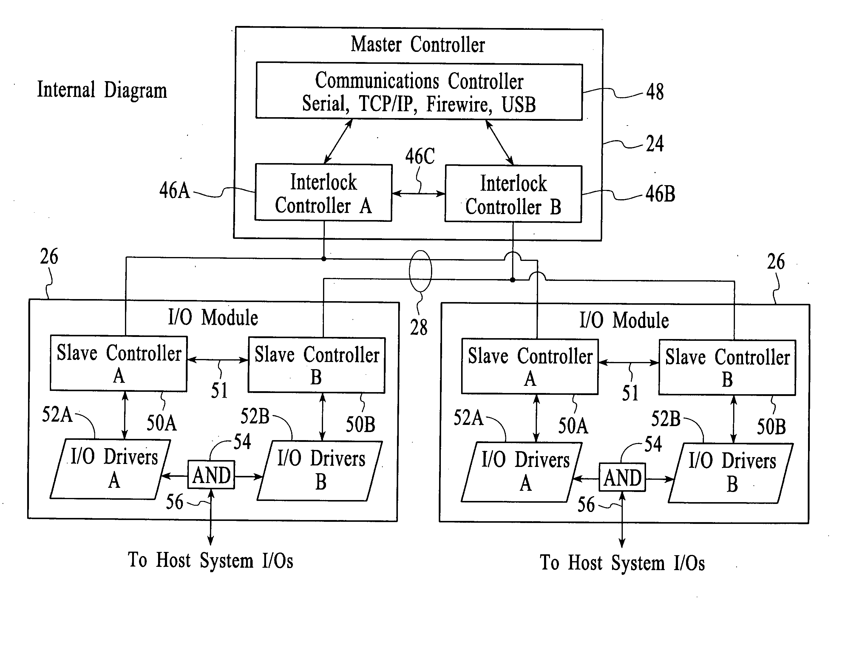
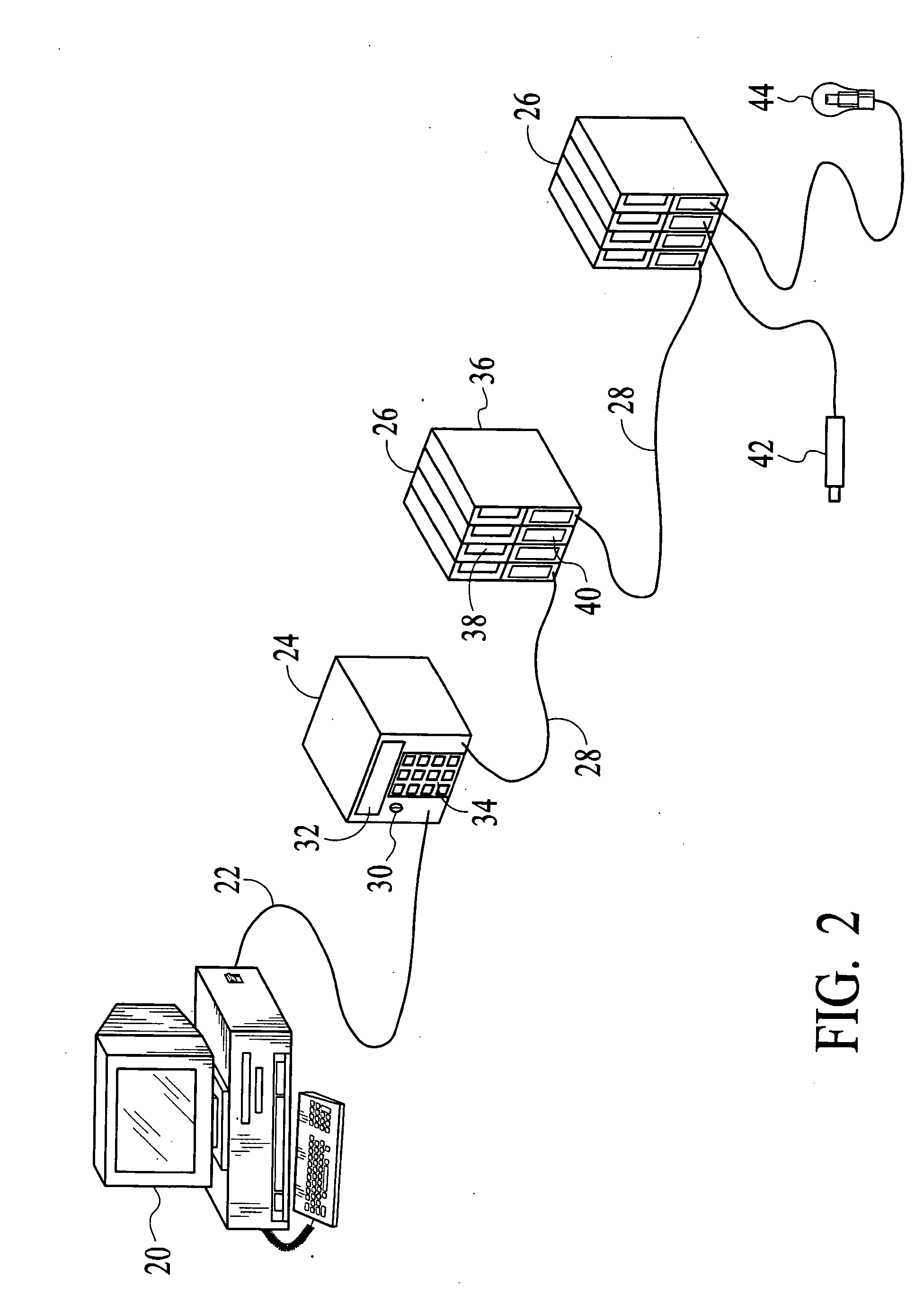
[0021] With reference to FIG. 2, an exemplary preferred embodiment of the present invention will now be described. While one particularly advantageous application of the present invention is for processing equipment such as for fabricating semiconductors, LCDs or other displays, electronics, medical devices, optical devices and the like, which typically include various chambers, chamber doors, heaters, robotic motors and actuators, gas flows, mass flow controllers and meters, timed events and the like, and much of the following discussion will be understood for such applications, it should be un...


PUM


Abstract

Apparatus and methods for controlling a system that operates responsive to a plurality of input control signals are disclosed. During operation the system generates a plurality of output status / control signals. A master controller has at least first and second controllers. The first controller outputs and inputs signals over a first communication path, and the second controller outputs and inputs signals over a second communication path. The first and second controllers output signals based on input signals received over the first and second communication paths, respectively, and also based on stored control data. A plurality of input / output modules are provided. Each of the input / output modules has first and second slave controllers. The first slave controller of each of the input / output modules inputs and outputs signals over the first communication path to the first controller, and the second slave controller outputs and inputs signals over the second communication path. Each of the first slave controllers outputs and inputs signals to and from a first input / output circuit, and each of the second slave controllers outputs and inputs signals to and from a second input / output circuit. Each of the input / output modules also includes a combiner circuit. At least some of the input control signals for controlling the system are generated by the combiner circuit of each input / output module based on signals output from both the first and second input / output circuits. The output control signals for controlling the system are generated based on output status / control signals from the system that are coupled to each of the first and second input / output circuits of the input / output modules.

Description

FIELD OF THE INVENTION [0001] The present invention relates to systems and methods utilizing inputs and outputs for purposes of controlling equipment (e.g., semiconductor process equipment), industrial machinery, processing lines and the like, and more particularly to input and output control systems and methods utilizing distributed input / output modules and integral interlocks. BACKGROUND OF THE INVENTION [0002] A variety of control systems for equipment, processing lines, assembly lines and the like have been proposed and utilized to varying degrees. For example, systems based on the use of digital computers and / or microprocessors / microcontrollers are known to provide a reasonably high degree of programmable input / output control for such applications. While the advances in this general field have been relatively great, due to reasons such as safety and conventional design practices, there are a number of undesirable attributes of such conventional control systems. [0003]FIG. 1 ill...

Claims


Application Information

Patent Timeline
Patent Type & Authority Applications(United States)
IPC IPC(8): G05B19/18G05B11/01G05B19/042
CPCG05B19/0421G05B2219/24187G05B2219/2231
Inventor DAVLIN, KARL A.TANNOUS, ADEL GEORGELOUDERMILK, ALAN R.
Owner EI ELECTRONICS
Why Eureka
Try Eureka