Seed tube guard assembly for agricultural planters

a technology for agricultural planters and shanks, applied in the field of agricultural planters, can solve the problems of excessive wear of the shank assembly, insufficient material wear resistance, and oversize sheet metal holes in the shank assembly, etc., to reduce the amount of maintenance required, prevent damage to the inner surface, and prolong the life

Active Publication Date: 2006-02-16
COPPERHEAD PLANTER PROD LLC
View PDF11 Cites 6 Cited by
  • Summary
  • Abstract
  • Description
  • Claims
  • Application Information

AI Technical Summary

Benefits of technology

[0014] It is a further object of the present invention to provide an improved seed tube guard assembly that has a long wear life, that prevents damage to the inner surface of the opener disks, that reduces maintenance required for the planter, that allows a furrow having a consistent width to be produced by the planter for a longer period of time for more accurate seed placement, that provides wide and narrow options to accommodate different opener assemblies, that has a durable mounting system for attaching to the planter shank, and that has wear plates which are simple to remove and replace.
[0015] To accomplish these and other objects of the invention, a seed tube guard assembly is provided for agricultural planters which has floating wear plates to improve the wear life of the seed tube guard assembly. The assembly includes a support bracket having an upper end attached to a planter shank assembly and a lower end positioned between a pair of opener disks. A seed tube guide extends rearwardly from the support bracket for receiving a lower end of a seed tube. A pair of dowels are pressed into openings near the lower end of the support bracket and protrude from the right and left sides of the support bracket. A metal ball is press fit into an opening in the support bracket between the dowels with opposite sides of the metal ball protruding from the right and left sides of the support bracket. The floating wear plates each have a pair of holes for mounting the wear plates over the dowels on the respective right and left sides of the support bracket with the protruding sides of the metal ball engaging the wear plates at respective fulcrum points between the dowels.
[0016] According to a broad aspect of the present invention, a seed tube guard assembly for an agricultural planter is provided, comprising: a support bracket having an upper end adapted to be attached to a planter shank assembly and a lower end adapted to be positioned between a pair of opener disks; a seed tube guide extending from a rear side of the support bracket for centering a seed tube between the pair of opener disks, preventing seed falling from the seed tube from contacting inner surfaces of the opener disks, and preventing soil from falling into a furrow made by the opener disks before seed has been placed in the furrow; and first and second floating wear plates disposed on respective right and left sides of the support bracket in front of the seed tube guide for engaging inner surfaces of the opener disks of the planter.

Problems solved by technology

This is due primarily to the inadequate wear resistance of the material and also the small wear surface 27.
The oversize sheet metal holes 25 in the shank assembly 23 are also subject to excessive wear.

Method used


Image

  • Seed tube guard assembly for agricultural planters
  • Seed tube guard assembly for agricultural planters
  • Seed tube guard assembly for agricultural planters

Examples


Embodiment Construction

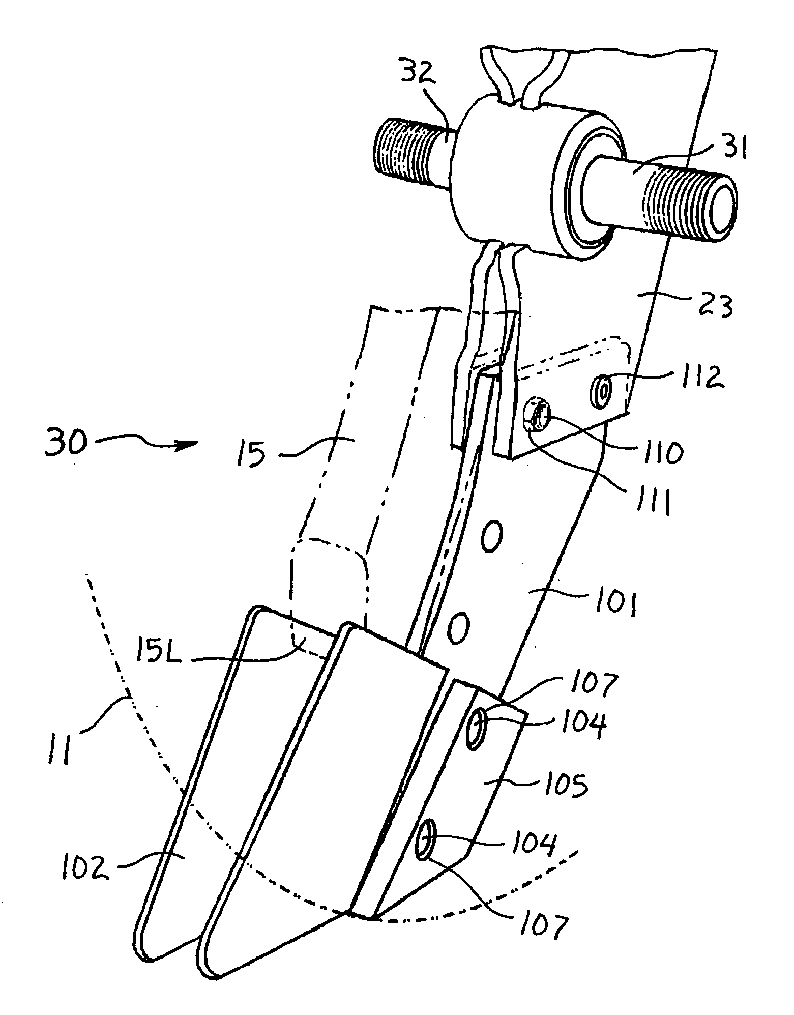
[0031] An improved seed tube guard assembly 30 according to the present invention will now be described in detail with reference to FIGS. 1, 2 and 5 to 12 of the accompanying drawings.

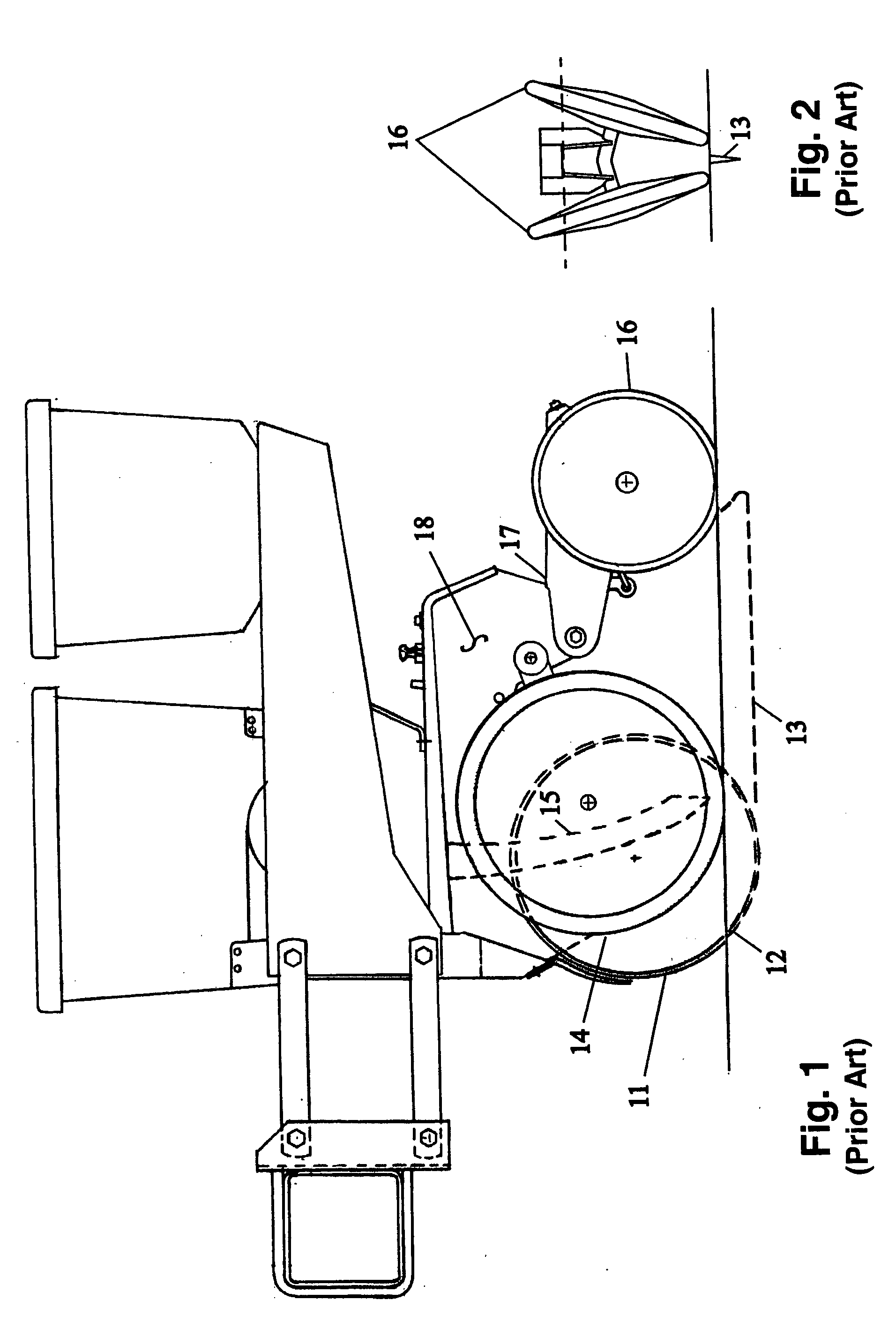
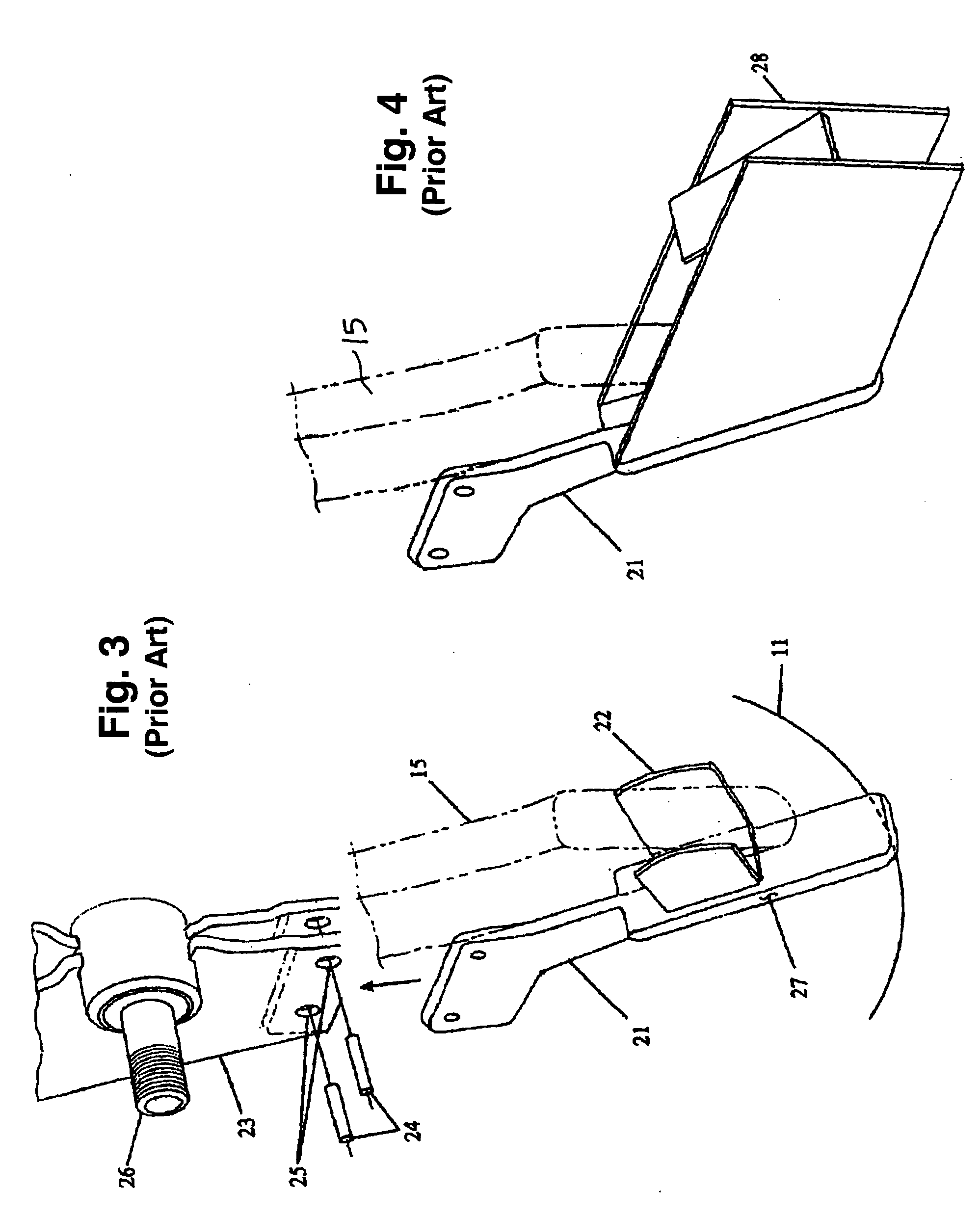
[0032] The seed tube guard assembly 30 of the present invention is mounted to a planter shank 23 of an agricultural planter between two opener disks 11 used to form a furrow 13 (see FIGS. 1 and 2) in soil for planting seeds. The opener disks 11 are rotatably mounted on respective right and left spindles 31, 32 attached to the planter shank 23 in a conventional manner. The lower end of the shank 23 has a slot 33 formed between right and left sides thereof for receiving an upper end portion of a support bracket 101 of the seed tube guard assembly 30. Openings 34 are provided in the lower end of the shank 23 to match the openings 35 provided in the upper portion of the support bracket 101 for attaching the support bracket 101 to the shank 23. The support bracket 101 can be formed, for example, of heat-tr...


PUM


Abstract

A seed tube guard assembly for agricultural planters has floating wear plates to improve the wear life of the seed tube guard. The assembly includes a support bracket having an upper end attached to a planter shank assembly and a lower end positioned between a pair of opener disks. A seed tube guide extends rearwardly from the support bracket for receiving a lower end of a seed tube. A pair of dowels are pressed into openings in the support bracket and protrude from the sides thereof. A metal ball is press fit into an opening in the support bracket between the dowels with opposite sides of the metal ball protruding from the respective sides of the support bracket. The floating wear plates are supported by the dowels on the respective sides of the support bracket with the metal ball engaging the wear plates at respective fulcrum points between the dowels.

Description

RELATED APPLICATIONS [0001] This application claims the benefit of the Applicant's U.S. provisional patent application Ser. No. 60 / 601,513 filed on Aug. 12, 2004.BACKGROUND OF THE INVENTION [0002] 1. Field of the Invention [0003] The present invention relates generally to agricultural planters. In particular, the present invention relates to seed tube guards with improved durability for use with agricultural planters. [0004] 2. Description of the Prior Art [0005] The first modern planter was the John Deere 7000 series introduced in 1973. It is depicted in FIGS. 1 and 2 of the accompanying drawings. This design utilizes two opener disks 11 that contact at one point 12 and diverge at a small angle to form a furrow 13 in the ground. The depth of the furrow is determined by the adjustable position of the gauge wheels 14. The seed is dropped into a seed tube 15 and falls into the furrow 13. A pair of closing wheels 16 are mounted at an angle behind the seed tube 15 and are spring-loaded ...

Claims


Application Information

Patent Timeline
Patent Type & Authority Applications(United States)
IPC IPC(8): A01C7/00A01C9/00
CPCA01C5/062A01C7/206A01C5/064
Inventor KESTER, PHILIP C.
Owner COPPERHEAD PLANTER PROD LLC
Why Eureka
Try Eureka