Retrofit hydraulic power take-off clutch

a technology of hydraulic power take-off and clutch, which is applied in the direction of fluid actuated clutches, clutches, non-mechanical actuated clutches, etc., can solve the problems of pilot bearing utilization, operator abuse, and high cost, and achieve the effect of rapid retrofit or replacemen

Inactive Publication Date: 2006-02-16
POWER TRANSMISSION TECH
View PDF4 Cites 23 Cited by
  • Summary
  • Abstract
  • Description
  • Claims
  • Application Information

AI Technical Summary

Benefits of technology

[0005] In light of the foregoing, it is the first aspect of the invention to provide a hydraulic dry power take-off clutch PTO which can be readily retrofitted or substituted for corresponding mechanically actuated dry over-center power take-off clutch.

Problems solved by technology

Such PTO's have been fraught with problems incident to the utilization of pilot bearings, necessary adjustments, and operator abuse.

Method used


Image

  • Retrofit hydraulic power take-off clutch
  • Retrofit hydraulic power take-off clutch
  • Retrofit hydraulic power take-off clutch

Examples


Embodiment Construction

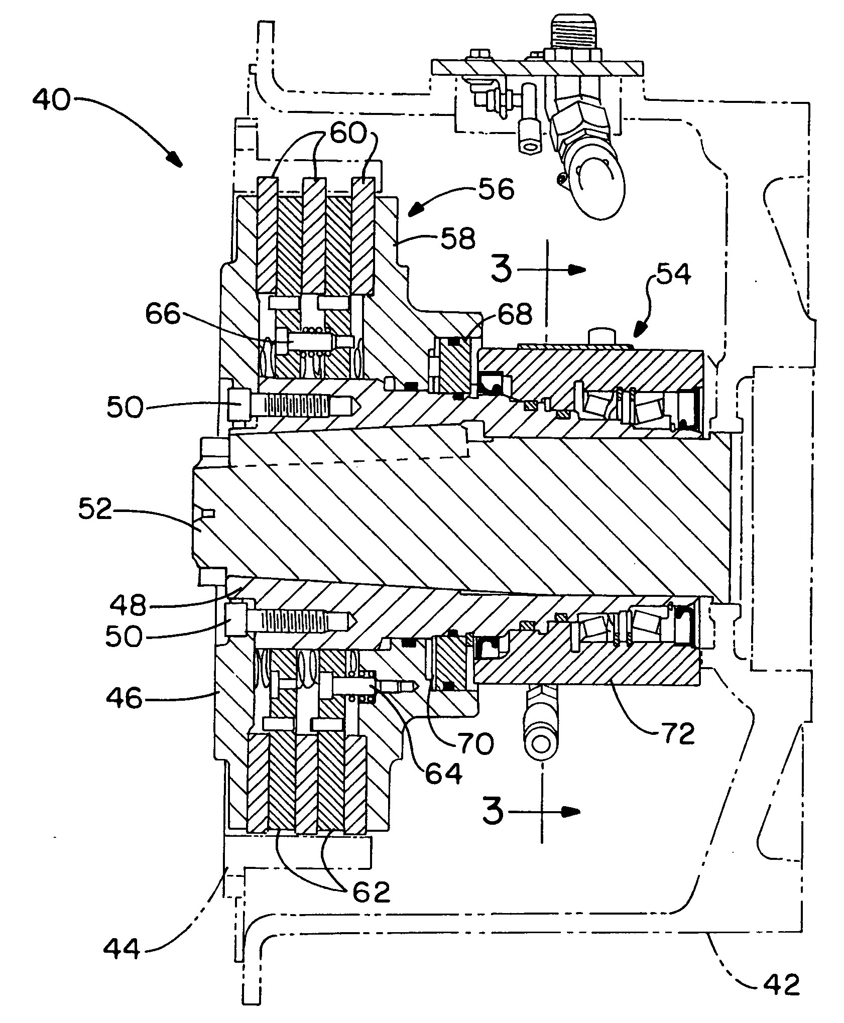
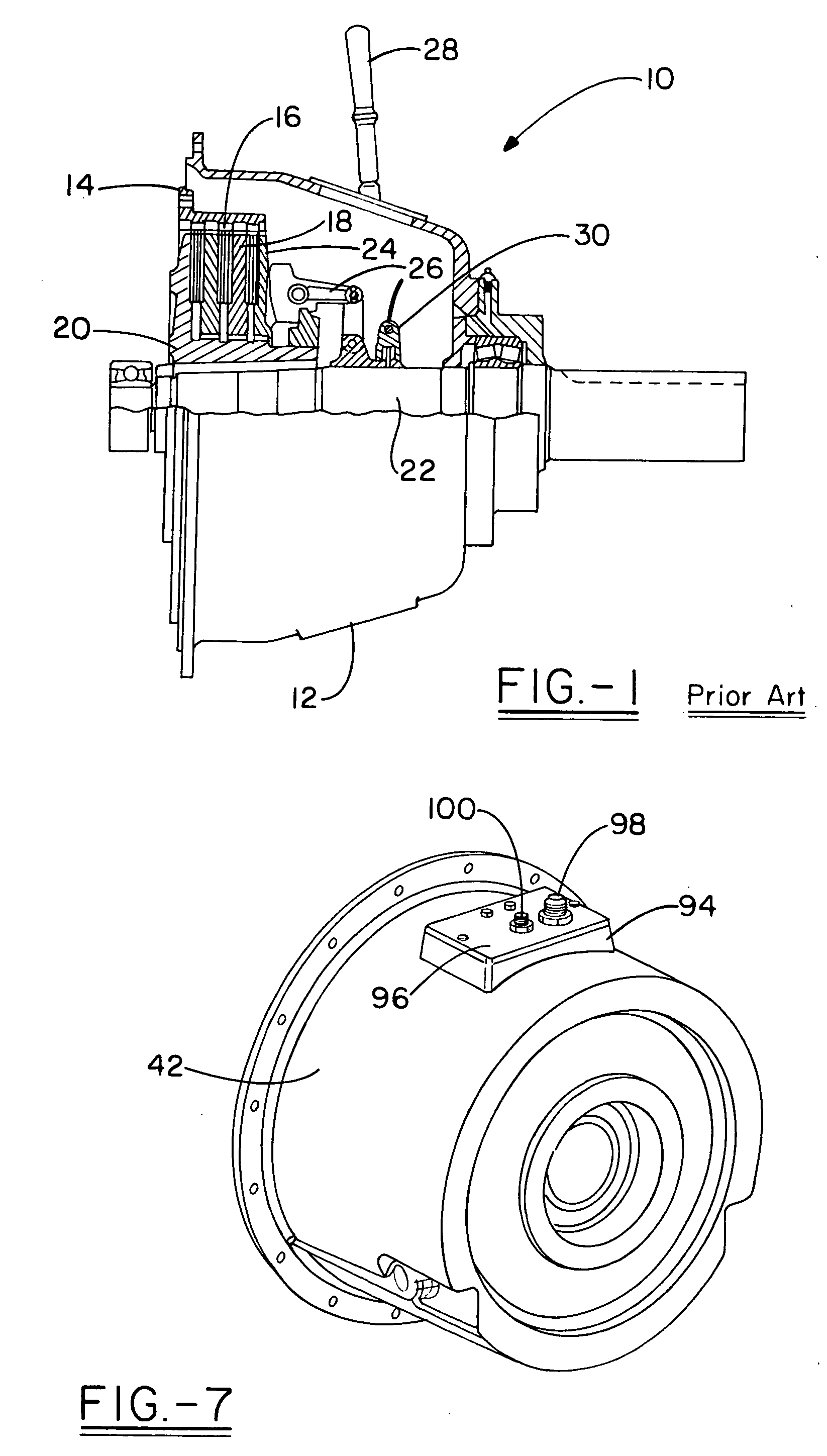
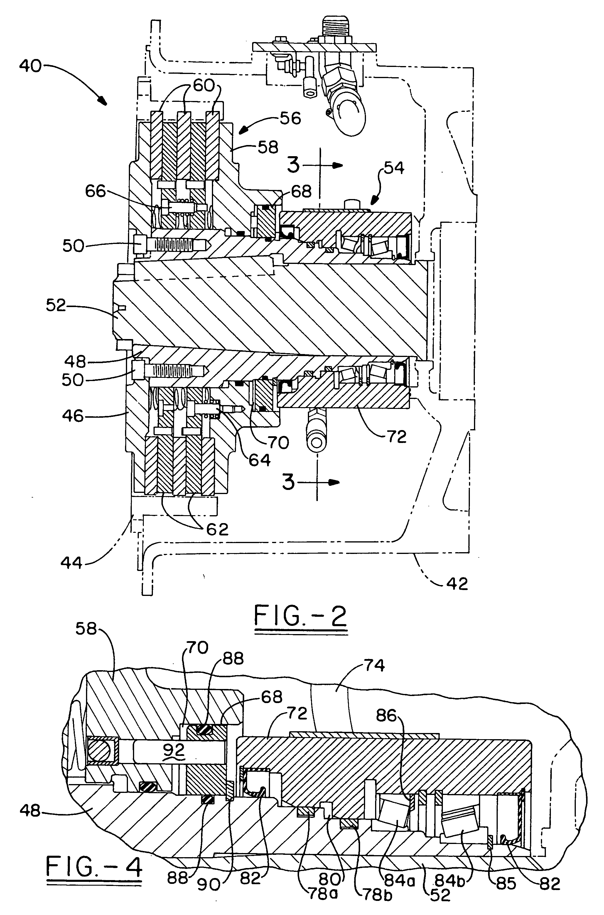
[0020] Referring now to the drawings and more particularly FIG. 1, it can be seen that a manually actuated power take-off device with an over-center clutch made in accordance with the prior art is designated generally by the numeral 10. The clutch 10 is a commercial embodiment of the clutch of prior U.S. Pat. No. 5,400,862, and corresponds to SAE J621d standard as to housing size, SAE J620 as to mounting bolt pattern, and SAE J617c as to drive flange configuration. The embodiment shown is general and adaptive to the power output that may be employed, whether skilled in the art will readily appreciate that the concept of the invention extends to coaxial drive shafts and other power outputs.

[0021] The clutch assembly 10 includes a bell housing 12 for maintaining the clutch mechanism therein. The bell housing 12 is adapted to be mounted to a power source such as an engine or the like and, in that regard, is provided with standard housing dimensions and mounting bolt spacings correspon...


PUM


Abstract

A hydraulic dry power take-off clutch is adapted to be retrofit for prior manually actuated dry over-center power take-offs in compliance with certain SAE specifications. Both the resultant clutch and a retrofit kit for effecting the same are presented. According to the invention, an input hub is securedly received upon a shaft with an end plate secured to the input hub. A drive flange is adapted for securement to a flywheel or power source. A hydraulically actuated clutch disk assembly is received by the input hub and is in interconnection with the dry flange. Finally, a rotary union is received upon an end of the input hub opposite that of the clutch disk assembly, the rotary union providing a conduit for passing pressurized hydraulic fluid to the clutch disk assembly. The entire structure is adapted to be received within the same bell housing, and to employ the same drive ring as the prior art dry over-center power take-off units.

Description

TECHNICAL FIELD [0001] The invention herein resides in the art of power transmission devices and, more particularly, to clutch systems interposed between a power source and load to selectively transfer the power from the source to the load. More particularly, the invention relates to a hydraulically actuated power take-off clutch system, and more specifically, to such a hydraulic clutch system adapted for replacement of a manually actuated over-center clutch within the housing and envelope of the manually actuated clutch. BACKGROUND ART [0002] Dry over-center power take-off clutches are in common use from the largest engine driven industrial type employed with shredders and grinders, to simpler smaller machines of all types and natures. Such PTO's have been fraught with problems incident to the utilization of pilot bearings, necessary adjustments, and operator abuse. [0003] A multitude of such over-center power take-off clutches continue in use with the inherent problems just descri...

Claims


Application Information

Patent Timeline
Patent Type & Authority Applications(United States)
IPC IPC(8): F16D25/0638
CPCF16D25/0638
Inventor GUINTER, JOSEPH W.HERCHICK, ROBERT E.HEIDENREICH, DAVID C.
Owner POWER TRANSMISSION TECH
Why Eureka
Try Eureka