Eureka AIR delivers breakthrough ideas for toughest innovation challenges, trusted by R&D personnel around the world.

Mixed solution for a display device and method for fabricating a display device by using the same

a technology of mixing solution and display device, which is applied in the direction of luminescent compositions, coatings, chemistry apparatus and processes, etc., can solve the problems of difficult to dissolve a certain amount or more of solute in some cases, difficult to apply a solution having a high concentration and high viscosity, and achieve uniform organic layer, easy to check, and high viscosity

Inactive Publication Date: 2006-02-16
OPTREX CORP
View PDF8 Cites 12 Cited by
  • Summary
  • Abstract
  • Description
  • Claims
  • Application Information

AI Technical Summary

Benefits of technology

[0017] The present invention is proposed in consideration of the problem stated above. It is an object of the present invention to provide a mixed solution for a display device and a method for fabricating a display device by using the same, which are capable of uniformly applying an organic material and decreasing the occurrence of degradation in display quality caused by non-uniformity in a film thickness.
[0033] In accordance with the present invention, it is possible to provide a mixed solution and a method for fabricating a display device by using the same, which are capable of uniformly applying an organic material.

Problems solved by technology

When such a solution is wet-applied by, e.g., a spray applicator, it is difficult to apply a solution having a high concentration and a high viscosity.
Accordingly, when an organic material solution having a low viscosity is applied after formation of the separators 100, there is caused a problem that the applied solution spreads along the separators 100.
On the other hand, even when an attempt is made to use a solution having a high viscosity, it is impossible to dissolve a certain amount or more of solute in some cases.
Additionally, it is impossible to uniformly apply a solution having a high viscosity by some of applicators.
In the conventional organic EL display devices, non-uniformity in light emission is caused by non-uniformity in a film thickness, which is created when the liquid material for forming an organic film flows out of an active area as stated above.
This has caused a problem that display quality is degraded.

Method used


Image

  • Mixed solution for a display device and method for fabricating a display device by using the same
  • Mixed solution for a display device and method for fabricating a display device by using the same
  • Mixed solution for a display device and method for fabricating a display device by using the same

Examples


Embodiment Construction

[0042] Now, an embodiment, to which the present invention is applicable, will be described. The following description is provided for explanation of embodiments of the present invention, and the present invention is not limited to the embodiments described below.

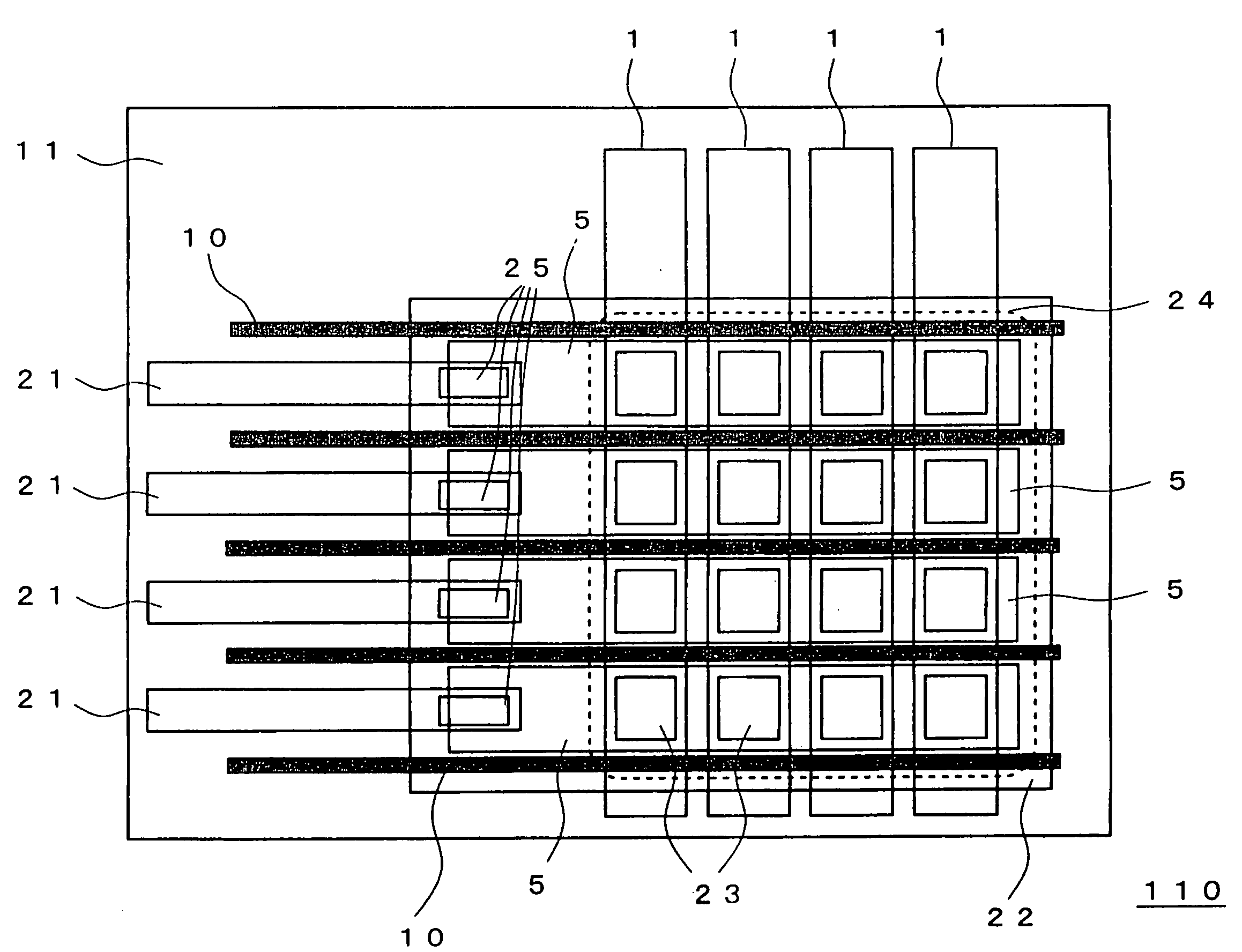
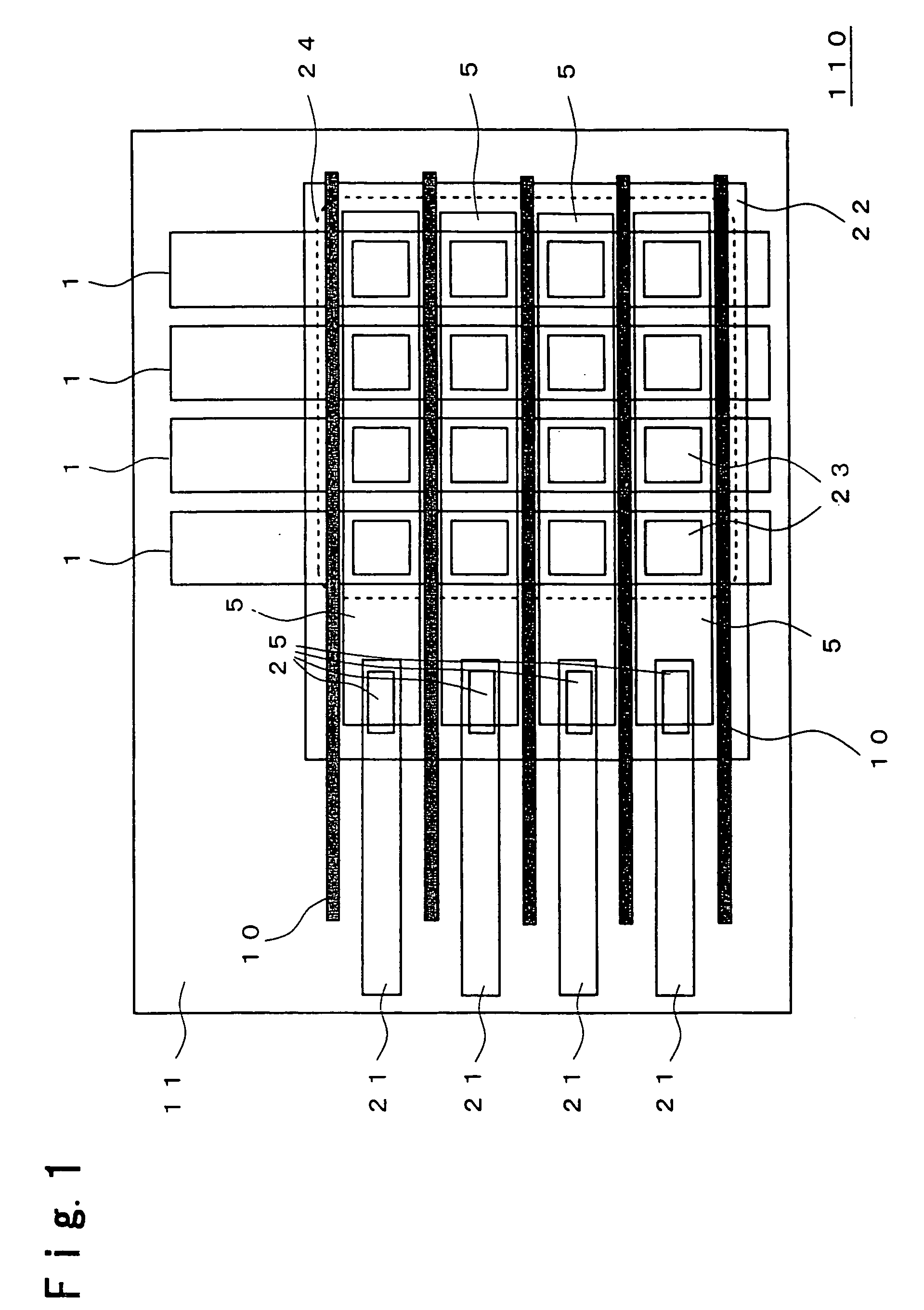
[0043] A panel substrate, on which the organic EL light emitting panel of the organic EL display device according to an embodiment of the present invention is disposed, will be described, referring to FIG. 1. FIG. 1 is a plan view showing the structure of the panel substrate 110 of the organic EL display device. Reference numeral 1 designates an anode wire, reference numeral 5 designates a cathode wire, reference numeral 10 designated a separator, reference numeral 11 designates the substrate, reference numeral 21 designates a cathode connection wire, reference numeral 22 designates an insulating film, reference numeral 23 designates an apertural area, reference numeral 24 designates an active area indicated by a dotted lin...


PUM


Abstract

One mode of the fabricating method according to the present invention comprises the steps of spraying a solution in which a solute forming a least one portion of an organic layer is dissolved; and drying the substrate to evaporate the solvent contained in the sprayed solution; wherein the solution comprises a first solvent capable of dissolving the solute by 1 mass % or above and a volatile solvent capable of completely volatilizing before the sprayed solution has been arrived on the substrate.

Description

BACKGROUND OF THE INVENTION [0001] The present invention relates to a mixed solution for a display device and a method for fabricating a display device by using the same. [0002] For recent years, research and development has been actively conducted on organic EL display devices using an organic EL panel. Organic EL display devices are expected to be the next generation of display devices because of having a wider viewing angle range and faster response than liquid crystal display devices and because of an organic substance having a wide variety of light emission properties. An organic EL panel used in organic EL display devices has anodes disposed on a substrate, and an organic light-emitting layer formed on the substrate, the organic light emitting layer comprising organic multi-layer thin films. The organic EL panel is configured to have cathodes disposed on the organic multi-layer thin films so as to confront the anodes disposed on the substrate. The organic EL panel is a current...

Claims


Application Information

Patent Timeline
IPC IPC(8): B05D5/12C09K11/06
CPCH01L27/3281H01L51/56H01L51/5088H01L51/0007H10K59/17H10K71/15H10K50/17H05B33/10H10K71/00
Inventor HARADA, KORETOMOOTANI, SHINJUMONZEN, KAZUHIRO
Owner OPTREX CORP
Why Eureka
Eureka Blog
Learn More