Metal part and surface treating method thereof

a surface treatment method and metal technology, applied in the direction of insulating substrate metal adhesion improvement, manufacturing tools, transportation and packaging, etc., can solve the problems of insufficient adhesive inability to form a good adhesive layer, weak contact force between the metal and the adhesive agent, etc., to achieve increase the surface roughness, increase the anchoring effect, increase the surface area

Inactive Publication Date: 2006-02-16
NOK CORP
View PDF1 Cites 4 Cited by
  • Summary
  • Abstract
  • Description
  • Claims
  • Application Information

AI Technical Summary

Benefits of technology

[0035] ① An effect of increasing a surface area, that is, an adhesive area generated by an increase of surface roughness.
[0036] ② An effect of increasing an anchor generated by an increase of surface irregularity due to the increase of surface roughness.
[0037] ③ An effect of preventing an adhesive agent from flowing but generated by an increase of adhesive agent flow resistance caused by the increase of surface roughness.
[0038] Further, since the structure is made such that the surface roughness is transcribed into the rubber forming portion of the metal part by previously providing with the surface roughness in the corresponding portion of the mold to work the metal part, it is possible to make it easy to form the surface roughness in a specific portion of the metal part, and it is possible to achieve an improvement of working accuracy in the surface roughness, an improvement of mold maintenance property, a reduction of working cost, a reduction of man hour, and the like.
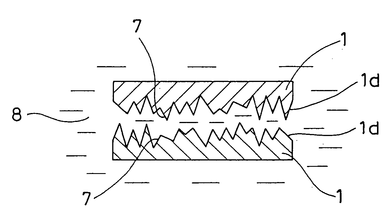
[0039] Further, on the basis of the metal part or the surface treating method in accordance with the eighth aspect to the thirteenth aspect of the present invention provided with the structure mentioned above, since the contact area between the metal parts is reduced and the bonding possibility due to the adhesive agent is reduced by forming the surface roughness in the contact surface of the metal part, it is possible to prevent a bonding failure in which the metal parts are bonded to each other from occurring.
[0040] Further, since the surface roughness is previously provided in the corresponding portion of the mold for working the metal part and the surface roughness is transcribed from the mold to the contact surface of the metal part, it is possible to make it easy to form the surface roughness in a specific portion of the metal part, and further it is possible to achieve an improvement of working accuracy in the surface roughness, an improvement of mold maintenance property, a reduction of working cost, a reduction of man hour and the like.

Problems solved by technology

In a product such as an oil seal, a gasket or the like in which a rubber is formed on a metal, a sufficient adhesive force can not be obtained between the metal and the rubber by forming the rubber directly on the metal.
Further, in the case of directly applying the adhesive agent onto the metal surface, a contact force between the metal and the adhesive agent is weak, and it is impossible to form a good adhesive layer.
However, in the conventional metal part, the metal part and the rubber are not sufficiently adhered and an adhesive failure occurs because of the following reasons.
② A physical contacting force (an anchor effect) between the adhesive layer and the metal surface (after the preliminary treatment) is insufficient.
Further, in the conventional metal part, a certain level (magnitude) of irregularity is applied to the surface of the metal part in accordance with the preliminary treatment (the zinc phosphate treatment or the shot blast treatment) or the like for the purpose of forming the good adhesive film as mentioned above, however, it is impossible to sufficiently obtain an effect of preventing the items ① to {circle around (3)} mentioned above in this level of irregularity.
Further, on the contrary, when the whole of the metal part is largely roughened for the purpose of obtaining an enough effect of preventing the items ① to ③ mentioned above, there occurs a trouble such as a rubber leakage at a time of molding, a size failure in the metal part, a deformation of the metal part or the like, so that this method can not be employed.
Further, the zinc phosphate treatment or the shot blast treatment has been conventionally carried out as mentioned above for the method of roughening the surface of the metal part, however, it is hard to work only a specific part of the metal, and a lot of man hour is required for keeping a working accuracy (roughness) and maintaining the apparatus.
Further, since an independent working step is provided, as a matter of course, a working cost and a working time are increased.
This bonding failure frequently occurs particularly in the case that the metal ring d is in a thin and flat shape and is small.
Against the bonding failure, there has been developed an adhesive agent by which the bonding is hard to occur, for the conventional bonding prevention measure, however, a complete countermeasure for all of the products has not been yet carried out due to the product functions.
Further, in this “disassembling step”, since a magnitude of the impact which can be applied thereto is limited (it is necessary that a magnitude of the applied impact should not be so large as the metal ring d is deformed), it is a reality that a sufficient effect can not be obtained for the metal ring d which has a thin and flat shape and is small.

Method used


Image

  • Metal part and surface treating method thereof
  • Metal part and surface treating method thereof
  • Metal part and surface treating method thereof

Examples


first embodiment

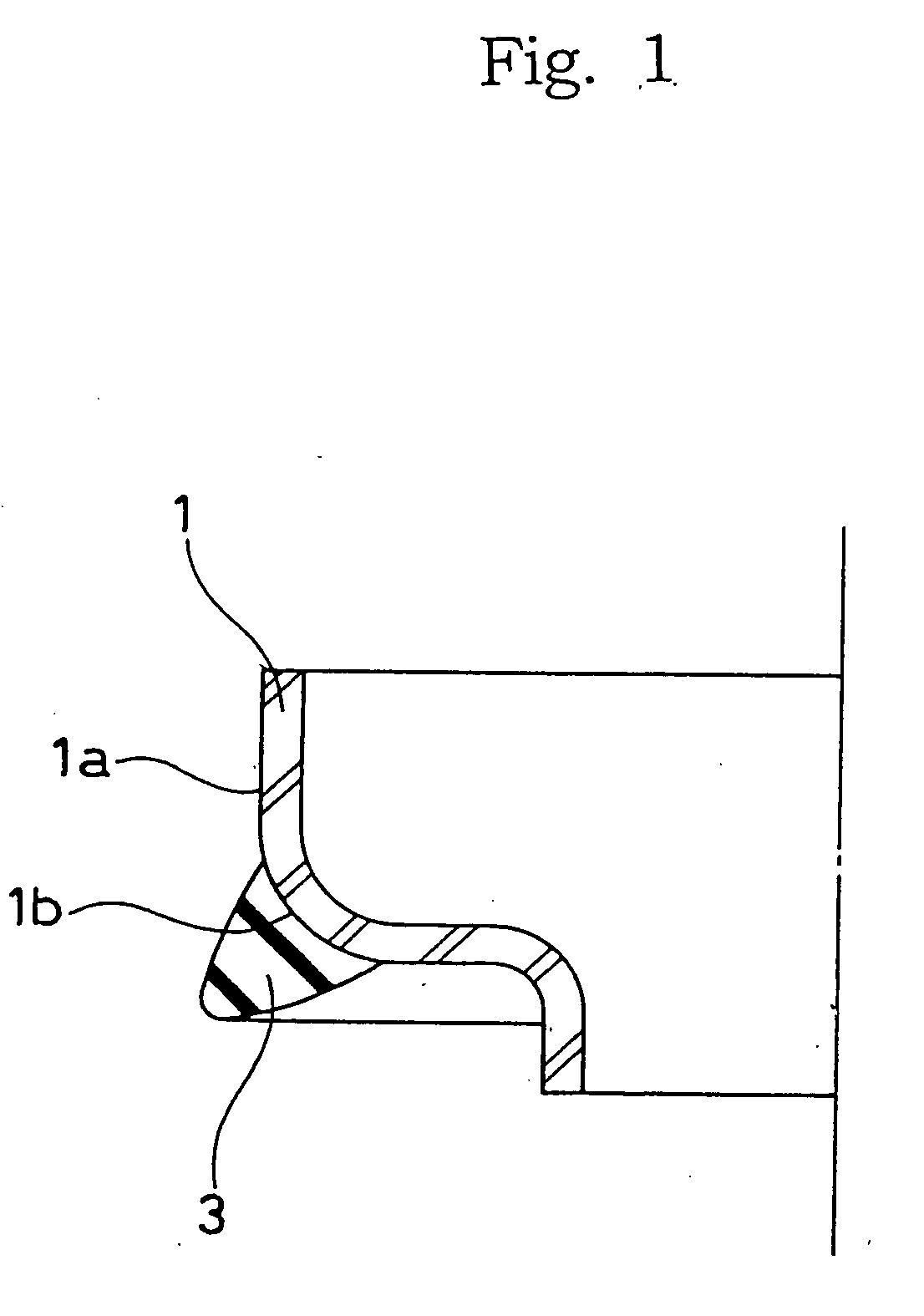
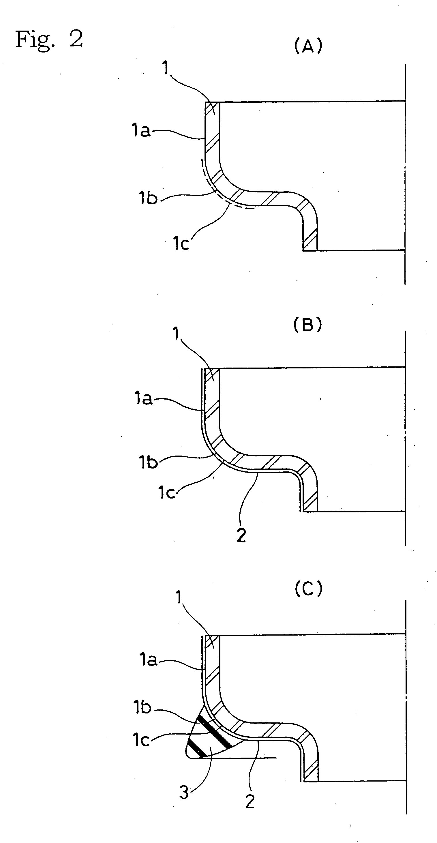
[0051]FIG. 1 is a half cut cross sectional view of a product such as a sealing apparatus provided with a metal part in accordance with a first embodiment of the present invention, and FIGS. 2A, 2B and 2C are schematic views showing manufacturing steps of the product in this order.

[0052] As shown in FIG. 1, a metal part in accordance with the embodiment is constituted of a metal ring 1 formed by punching and pressing a rolled steel corresponding to a raw material, and a surface roughness (also simply called as a roughness, not shown) which is determined in the following description is formed in a portion (a rubber adhesion portion) 1b in a surface 1a of the metal ring 1 to which a rubber 3 is adhered.

[0053] As shown in FIG. 2A, the metal ring 1 with a surface roughness 1c being formed in the rubber adhesion portion 1b is next exposed to an adhesion treatment, or a zinc phosphate treatment or a shot blast treatment and an adhesion treatment, as shown in FIG. 2B, whereby an adhesive ...

second embodiment

[0085]FIG. 5 shows a half cut cross section of a metal ring 1 corresponding to a metal part in accordance with a second embodiment of the present invention. A surface roughness 7 is formed in a contact surface 1d corresponding to a portion of a surface of the metal ring 1. An illustrated metal ring 1 is structured such that an outward flange-like collar portion 5 is provided in one end in an axial direction of a tubular portion 4 and an inward flange-like collar portion 6 is provided in another end in an axial direction of the tubular portion 4. Since an end surface of the latter inward flange-like collar portion 6 is considered as a contact surface 1d which possibly contacts with another metal ring (not shown) to be bonded, the surface roughness 7 is provided in the contact surface 1d.

[0086] The metal ring 1 is formed, as shown in FIG. 6, by punching and pressing a rolled steel 1′ corresponding to the raw material, and a manufacturing apparatus 11 thereof is, for example, structur...


PUM

PropertyMeasurementUnit
surface roughnessaaaaaaaaaa

Abstract

In a metal part in which a rubber is adhered to a portion or the whole of a surface thereof, and a surface treating method of the metal part, in order to improve an adhesive property between the metal and the rubber, to make it easy to form a surface roughness in a specific portion of a metal part, and to achieve an improvement of working accuracy in the surface roughness, an improvement of mold maintenance property, a reduction of working cost, a reduction of man hour, and the like, a surface roughness for increasing an adhesive property between the metal and the rubber is formed in a portion of a surface of the metal part to which the rubber is adhered, and the surface roughness is transcribed from a mold for working the metal part to the metal part by previously providing with a surface roughness in the mold. A magnitude of the surface roughness is preferably set to be 10 μm or more and less than 60 μm.

Description

[0001] This is a divisional of application Ser. No. 10 / 181,429 filed Jul. 25, 2002 which in turn is a nationalization of PCT / JP01 / 00534 filed Jan. 26, 2001 and published in Japanese.TECHNICAL FIELD [0002] The present invention relates to a metal part and a surface treating method thereof. [0003] A metal part corresponding to a subject of the present invention is a metal part in which a rubber is adhered to a portion or the whole of a surface, or a metal part worked such that a plurality of metal parts are simultaneously dipped in an adhesive agent solution to apply the adhesive agent solution to a surface of each of the metal parts, and is used, for example, as a supporting part, a mounting part or the like which supports a rubber seal portion in a sealing device such as an oil seal, a gasket or the like. BACKGROUND ART [0004] In a product such as an oil seal, a gasket or the like in which a rubber is formed on a metal, a sufficient adhesive force can not be obtained between the met...

Claims


Application Information

Patent Timeline
Patent Type & Authority Applications(United States)
IPC IPC(8): B21D39/00B32B15/06B21D22/02B21D22/20B21D28/34
CPCB21D22/02B21D22/203B21D28/34Y10T428/12569Y10T428/12562Y10T428/12535Y10T428/28Y10T428/12472Y10T428/31678
Inventor SUGANO, NORIOWATANABE, TSUTOMUKAKIMOTO, MITSUO
Owner NOK CORP
Why Eureka
Try Eureka