
Spinal surgery system and method

a spine surgery and spine technology, applied in the field of spine surgery, can solve the problems of limited reliability of available techniques for anchoring implants in position within the spinal column, difficult to achieve precise positioning of devices anterior to the spinal cord using a posterior approach, and insufficient flexibility of the spine, so as to enhance the fixation of the expandably fillable element and increase the height dimension of the vertebral body.

Inactive Publication Date: 2006-02-16
SIEGAL TZONY
View PDF24 Cites 190 Cited by
  • Summary
  • Abstract
  • Description
  • Claims
  • Application Information

AI Technical Summary

Benefits of technology

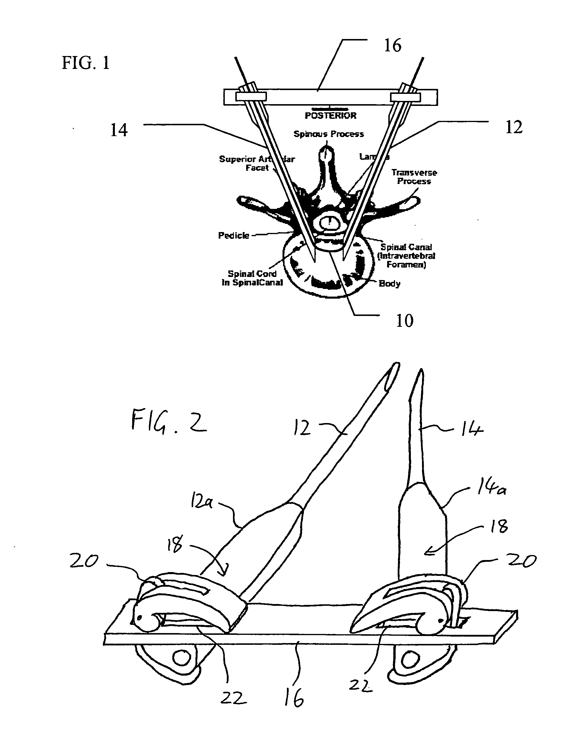
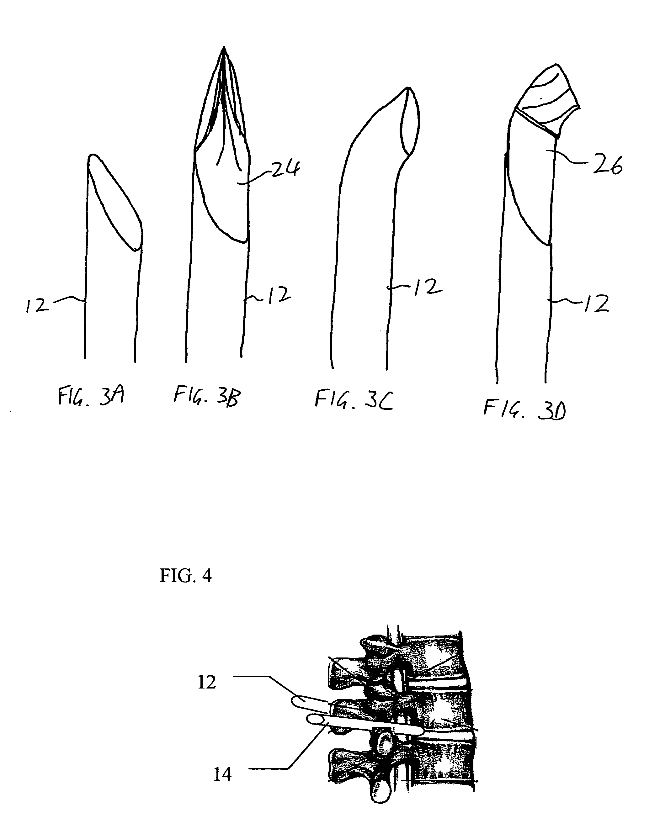
[0010] According to a further feature of the present invention, there is also provided a removable trocar removably receivable within each of the first and second tubes for facilitating insertion of the first and second tubes in the back of the patient.
[0053] According to a further feature of the present invention, the expandably fillable element has a plurality of perforations configured such that the inflation causes release of a small proportion of the filling material from the expandably fillable element so as to enhance fixation of the expandably fillable element.

Problems solved by technology

Despite a wide range of procedures performed today as minimally invasive spinal surgery (“MISS”) procedures, there remain fundamental limitations to the available options in a number of respects.
Firstly, while a posterior approach is preferred for minimizing iatrogenic soft-tissue morbidity, it has been found difficult to achieve precise positioning of devices anterior to the spinal cord using a posterior approach.
Furthermore, the available techniques for anchoring implants in position within the spinal column are limited in their reliability and tend to generate problematic local debris.

Method used


Image

  • Spinal surgery system and method
  • Spinal surgery system and method
  • Spinal surgery system and method

Examples


Embodiment Construction

[0067] The present invention is an apparatus and method for minimally invasive spinal surgery. The invention also provides surgical techniques, advantageously implemented using the apparatus and method of the invention, for intervertebral disc repair and for vertebral body repair.

[0068] The principles and operation of a surgical apparatus and method, and surgical techniques, according to the present invention will be better understood with reference to the drawings and the accompanying description.

Surgical Apparatus and Method

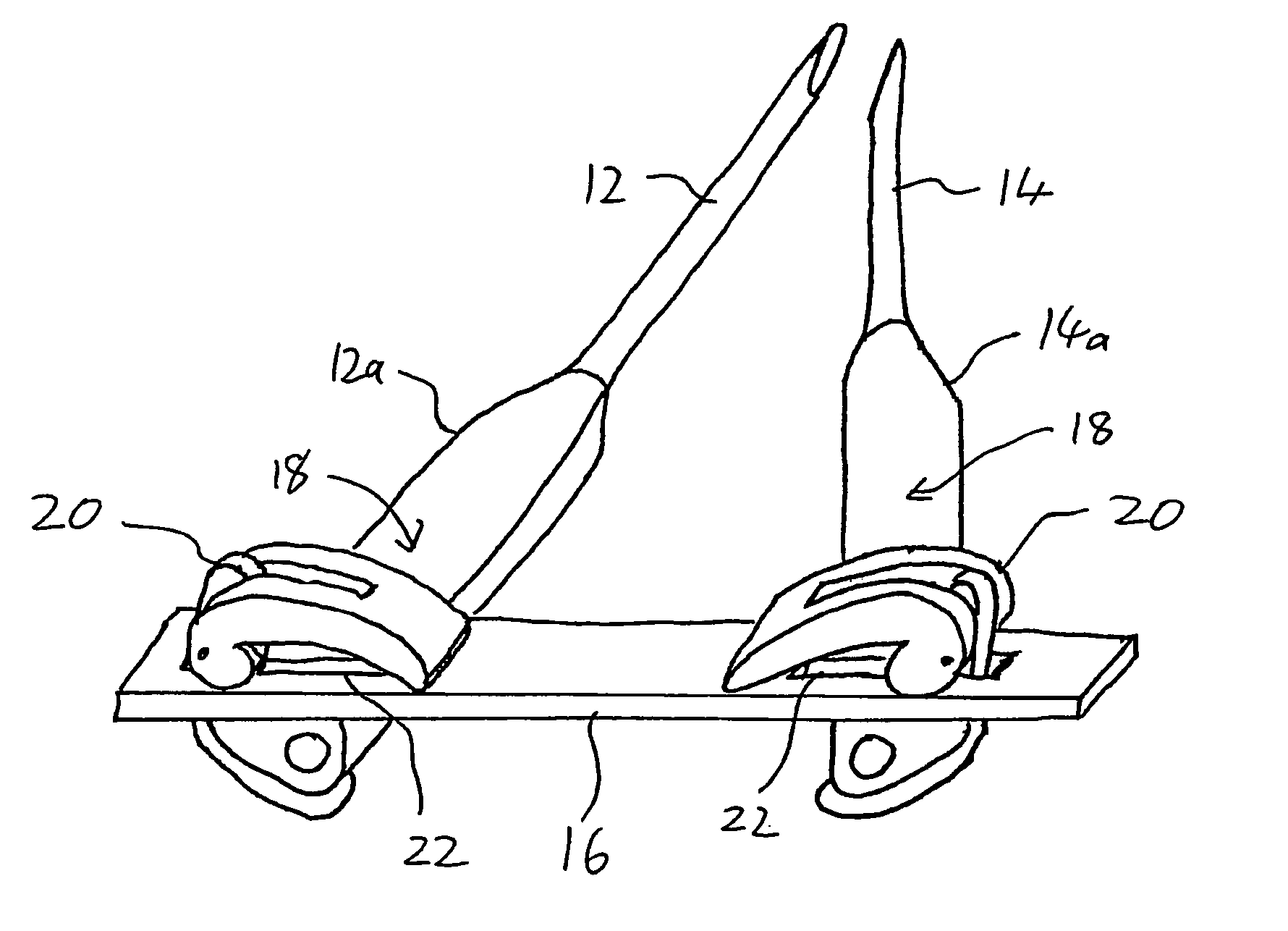
[0069] Referring now to the drawings, FIG. 1 illustrates a preferred apparatus and corresponding method for performing various minimally invasive spinal surgery (MISS) procedures according to the teachings of the present invention. In general terms, the preferred surgical method of the present invention is based on inserting an elongated flexible guide element 10 such that the guide element passes in through a first lateral posterior incision, passes throug...


PUM


Abstract

Apparatus and method for minimally invasive spinal surgery employs an elongated flexible guide element inserted so as to pass in through a first lateral posterior incision, through the spinal column anterior to the spinal cord, and out through a second lateral posterior incision contralateral to said first incision. The guide element is used to guide various elements to a desired position within the spinal column as part of the surgical procedure. Preferably, two hollow rigid tubes rigidly coupled outside the body in converging relation are used to define a working gap within the spinal column through which the guide element passes. This provides a platform for manipulation of tissues and introduction of implants anterior to the spinal cord. Procedures described include reinforcement of a degenerative intervertebral disc and restoration of a damaged vertebral body.

Description

FIELD AND BACKGROUND OF THE INVENTION [0001] The present invention relates to spinal surgery and, in particular, it concerns a system and method for performing various minimally invasive spinal surgical procedures. [0002] The past several years have witnessed a multitude of novel ideas and techniques for improved care for patients with spinal conditions. Some of these advances have improved the quality of life of patients suffering from degenerative disk disease with disabling low back pain. The current trend is towards less invasive approaches with less iatrogenic soft-tissue morbidity, as compared to traditional procedures with or without fusion of vertebral bones. [0003] Despite a wide range of procedures performed today as minimally invasive spinal surgery (“MISS”) procedures, there remain fundamental limitations to the available options in a number of respects. Firstly, while a posterior approach is preferred for minimizing iatrogenic soft-tissue morbidity, it has been found di...

Claims


Application Information

Patent Timeline
IPC IPC(8): A61F2/30
CPCA61B17/1642A61B17/1671A61B17/1757A61B17/7094A61F2250/0098A61F2002/30242A61F2002/4415A61F2002/444A61F2230/0071A61F2002/3008
Inventor SIEGAL, TZONY
Owner SIEGAL TZONY
Learn More