Method and apparatus for load reduction in an electric power system

a technology of electric power system and load reduction, applied in the field of monitoring system, can solve the problems of reducing the overall efficiency of the system, increasing the cost of operating the system, and increasing the cost of providing electricity

Active Publication Date: 2006-02-16
COPELAND LP
View PDF41 Cites 84 Cited by
  • Summary
  • Abstract
  • Description
  • Claims
  • Application Information

AI Technical Summary

Benefits of technology

[0011] These and other problems are solved by a real-time monitoring system that monitors various aspects of the operation of a refrigerant system, such as, for example, an HVAC system, a refrigerator, a cooler, a freezer, a water chiller, etc. In one embodiment, the monitoring system is configured as a retrofit system that can be installed in an existing refrigerant system.

Problems solved by technology

One of the major recurring expenses in operating a home or commercial building is the cost of providing electricity to the Heating Ventilating Air Conditioning (HVAC) system.
If the HVAC system is not operating at peak efficiency, then the cost of operating the system increases unnecessarily.
Situations that can reduce the overall efficiency of the system include, refrigerant overcharge, refrigerant undercharge, restrictions in refrigerant lines, faulty compressor, excessive load, insufficient load, undersized or dirty duct work, clogged air filters, etc.
Unfortunately, modern HVAC systems do not include monitoring systems to monitor the operating of the system.
This assumption can be expensive; as the owner has no knowledge of how well the system is functioning.
If the efficiency of the system deteriorates, the system may still be able to produce the desired amount of cold air, but it will have to work harder, and consume more energy, to do so.
In many cases, the system owner does not have the HVAC system inspected or serviced until the efficiency has dropped so low that it can no longer cool the building.
Even if the owner does pay for a service call, many HVAC service technicians do not measure system efficiency.
Typically, the HVAC service technicians are trained only to make rudimentary checks of the system (e.g., refrigerant charge, output temperature), but such rudimentary checks may not uncover other factors that can cause poor system efficiency.
Thus, the typical building owner, or home owner, operates the HVAC system year after year not knowing that the system may be wasting money by operating at less than peak efficiency.
Moreover, inefficiency use of electrical power can lead to brownouts and blackouts during heat waves or other periods of high air conditioning usage due to overloading of the electric power system (commonly referred to as the electric power grid).

Method used


Image

  • Method and apparatus for load reduction in an electric power system
  • Method and apparatus for load reduction in an electric power system
  • Method and apparatus for load reduction in an electric power system

Examples


Embodiment Construction

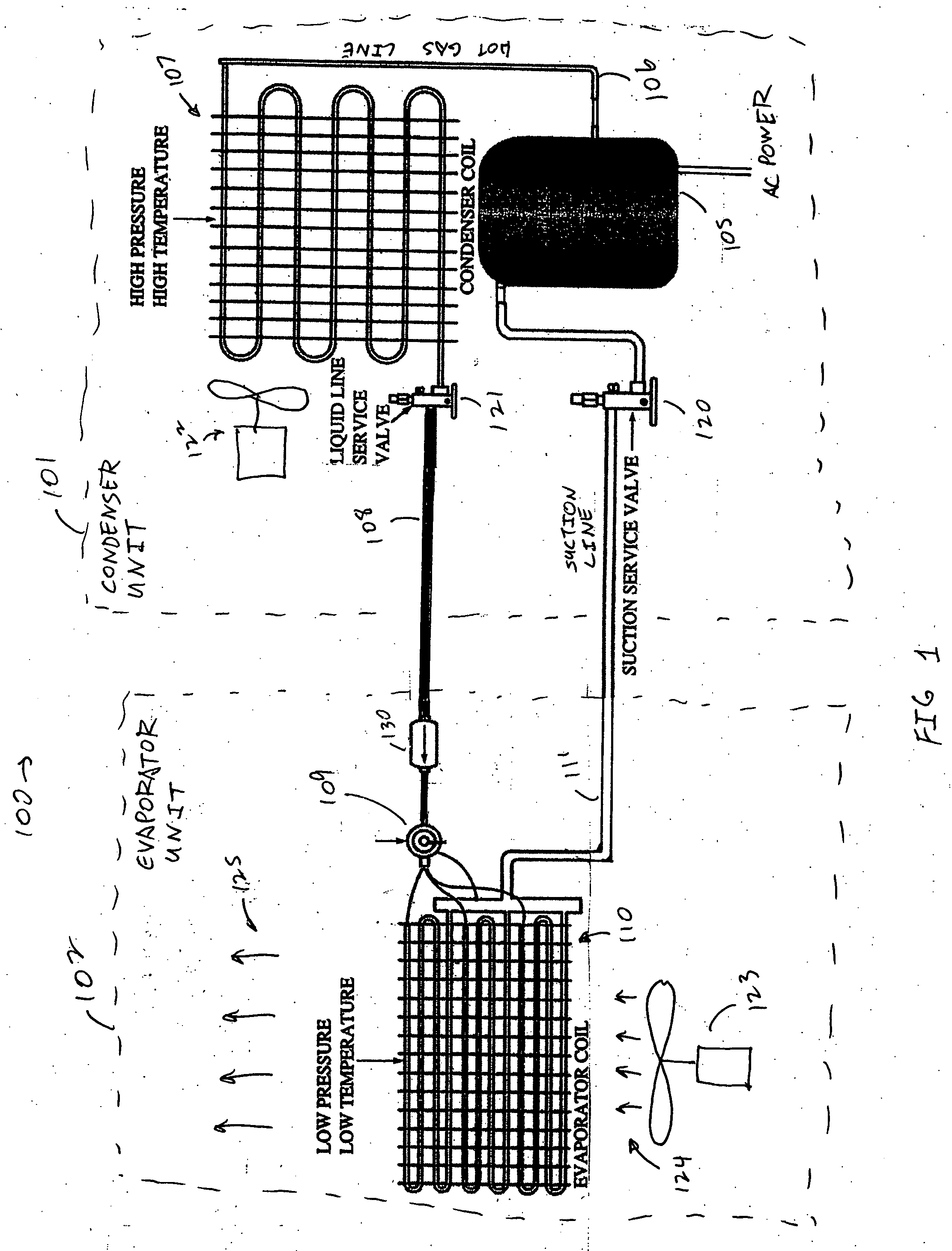
[0037]FIG. 1 is a diagram of a typical refrigerant cycle system 100 used in HVAC systems, refrigerators, freezers, and the like. In the system 100, a compressor provides hot compressed refrigerant gas to a hot gas line 106. The hot gas line provides the hot gas to a condenser 107. The condenser 107 cools the gas and condenses the gas into a liquid that is provided to a liquid line 108. The liquid refrigerant in the liquid line 108 is provided through a metering device 109 to an evaporator 110. The refrigerant expands back into a gas in the evaporator 110 and is provided back to the compressor though a suction line 110. A suction service valve 120 provides access to the suction line 111. A liquid line service valve 121 provides access to the liquid line 121. A fan 123 provides input air 124 to the evaporator 110. The evaporator cools the air and provides cooled evaporator output air 125. An optional drier / accumulator 130 can be provided in the liquid line 108. A fan 122 provides cool...


PUM


Abstract

A system for load control in an electrical power system is described, wherein one or more data interface devices are provided to a cooling system. The data interface devices are configured to receive commands for controlling the cooling system. A remote monitoring system, such as a monitoring system operated by a power company or a power transmission company sends one or more commands to the data interfaced devices to adjust loading on the electrical power system. In one embedment, the monitoring system sends shutdown commands. In one embedment, the monitoring system sends commands to tell a compressor in the cooling system to operate in a relatively low-speed mode. In one embedment, the monitoring system sends tell the compressor and / or the cooling system to operate in a relatively low-power mode. In one embodiment, the commands are time-limited, thereby allowing the cooling system to resume normal operation after a specified period of time. In one embodiment, the commands include query commands to cause the cooling system to report operating characteristics (e.g., efficiency, time of operation, etc.) back to the monitoring center.

Description

REFERENCE TO RELATED APPLICATION [0001] The entire contents of Applicant's copending U.S application No. ______, titled “METHOD AND APPARATUS FOR MONITORING REFRIGERANT-CYCLE SYSTEMS,” filed Aug. 11, 2004, are hereby incorporated by reference.BACKGROUND [0002] 1. Field of the Invention [0003] The invention relates to monitoring system for measuring the operating and efficiency of a refrigerant-cycle system, such as, for example, an air conditioning system or refrigeration system. [0004] 2. Description of the Related Art [0005] One of the major recurring expenses in operating a home or commercial building is the cost of providing electricity to the Heating Ventilating Air Conditioning (HVAC) system. If the HVAC system is not operating at peak efficiency, then the cost of operating the system increases unnecessarily. Each pound of refrigerant circulating in the system must do its share of the work. It must absorb an amount of heat in the evaporator or cooling coil, and it must dissipa...

Claims


Application Information

Patent Timeline
Patent Type & Authority Applications(United States)
IPC IPC(8): G05B15/00
CPCF25B49/005F25B2700/15F25B2700/1351F25B2600/07
Inventor KATES, LAWRENCE
Owner COPELAND LP
Why Eureka
Try Eureka