Resonance test system

a test system and resonance technology, applied in the field of structural load application systems to specimens, can solve the problems of reducing the time required for testing, reducing the scale of hydraulic testing systems of the type just described, and reducing the static and dynamic load of the larger blades associated with the larger wind generator systems

Active Publication Date: 2006-02-23
ALLIANCE FOR SUSTAINABLE ENERGY
View PDF27 Cites 93 Cited by
  • Summary
  • Abstract
  • Description
  • Claims
  • Application Information

AI Technical Summary

Benefits of technology

[0010] Apparatus for applying at least one load to a specimen according to one embodiment of the invention may comprise a mass. An actuator mounted to the specimen and operatively associated with the mass moves the mass along a linear displacement path that is perpendicular to a longitudinal axis

Problems solved by technology

Unfortunately, however, the larger blades associated with larger wind generator systems are subjected to greater static and dynamic loads.
Loads in more than one direction maybe applied simultaneously with such apparatus, which often reduces the time required for testing.
Unfortunately, however, hydraulic testing systems of the type just described are not readily scalable, and it is difficult to use such an apparatus to test larger blades.
For example, larger blades require larger deflections, thereby increasing the amount of hydraulic fluid that must be pumped to the actuators.
While larger pumps can be used, there is a limit to the maximum pump size that can be practically used, both from a power requirement standpoint and from the standpoint of pump system cost.
It is also difficult to provide actuators capable o

Method used


Image

  • Resonance test system
  • Resonance test system
  • Resonance test system

Examples


Embodiment Construction

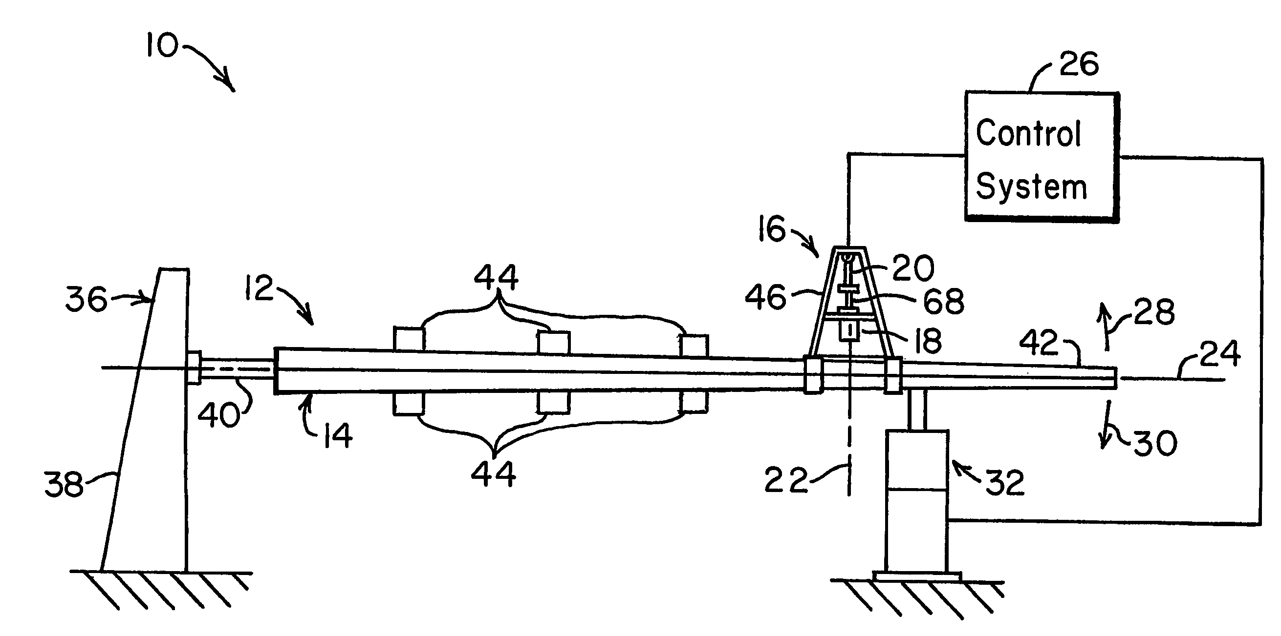
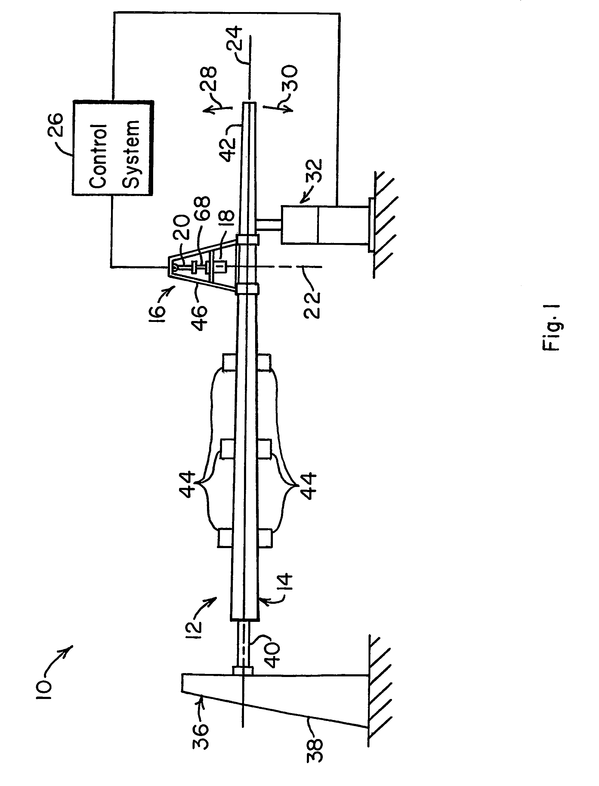
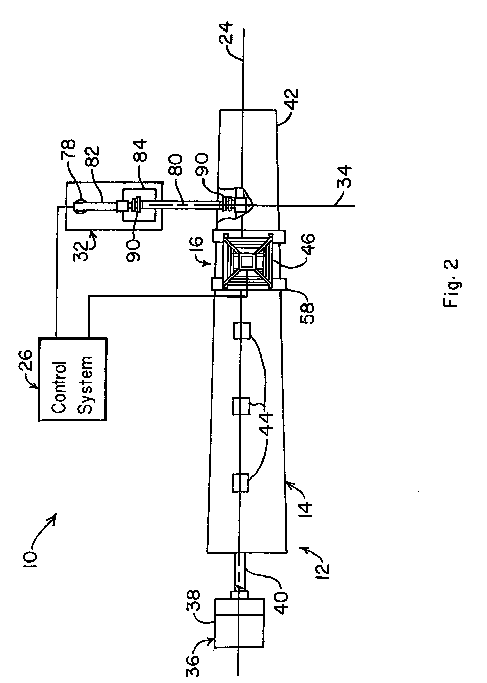
[0018] Apparatus 10 for applying at least one load to a specimen 12, such as a wind turbine blade 14, is best seen in FIGS. 1-4 and may comprise a resonant actuator system 16 having a mass 18 that is operatively associated with an actuator 20. The actuator 20 moves the mass 18 along a linear displacement axis or path 22 that is perpendicular to a longitudinal axis 24 of the wind turbine blade 14. A control system 26 operatively associated with the actuator 20 operates the actuator 20 to reciprocate the mass 18 along the linear displacement path 22 at a reciprocating frequency that is about equal to a resonance frequency of the specimen 12 (e.g., wind turbine blade 14) in a test configuration. The reciprocating mass 18 causes the wind turbine blade 14 to vibrate along the longitudinal axis 24, i.e., in the directions indicated by arrows 28 and 30, which results in the application to the specimen 12 (e.g., wind turbine blade 14) of bending or flap loads.

[0019] It is generally preferr...


PUM


Abstract

An apparatus (10) for applying at least one load to a specimen (12) according to one embodiment of the invention may comprise a mass (18). An actuator (20) mounted to the specimen (12) and operatively associated with the mass (18) moves the mass (18) along a linear displacement path (22) that is perpendicular to a longitudinal axis of the specimen (12). A control system (26) operatively associated with the actuator (20) operates the actuator (20) to reciprocate the mass (18) along the linear displacement path (22) at a reciprocating frequency, the reciprocating frequency being about equal to a resonance frequency of the specimen (12) in a test configuration.

Description

CONTRACTUAL ORIGIN OF THE INVENTION [0001] The United States Government has rights in this invention pursuant to Contract No. DE-AC36-99GO10337 between the U.S. Department of Energy and the Midwest Research Institute.TECHNICAL FIELD [0002] This invention relates to systems for applying structural loads to specimens and more specifically to a system for applying structural loads to wind turbine blades. BACKGROUND ART [0003] Wind-powered generator systems are well-known in the art and have been used for decades for generating electrical power from wind energy. While numerous configurations exist and have been used with varying degrees of success, most wind-powered generator systems utilize a rotor or impeller that is configured to rotate in a prevailing wind. An electrical generator connected to the rotor is rotated by the rotor and produces useful electrical power from the rotational movement of the rotor. [0004] A commonly used rotor design or configuration resembles an aircraft pro...

Claims


Application Information

Patent Timeline
IPC IPC(8): G01M7/02G01N3/32G01M7/00
CPCG01M7/00G01N3/34G01N2203/0073G01N2203/0023G01N2203/0039G01N2203/0005
Inventor MUSIAL, WALTERWHITE, DARRIS
Owner ALLIANCE FOR SUSTAINABLE ENERGY
Why Eureka
Try Eureka