Method of mounting tires to civil engineering vehicles and associated tire

a technology for civil engineering vehicles and tires, applied in the field of tread patterns, can solve the problems of marked influence on the wear of such tires and even more difficult rolling conditions, and achieve the effect of reducing slippage and consequent wear

Inactive Publication Date: 2006-02-23
MICHELIN RECH & TECH SA
View PDF15 Cites 23 Cited by
  • Summary
  • Abstract
  • Description
  • Claims
  • Application Information

AI Technical Summary

Benefits of technology

[0019] In effect, the load supported by the edge of the tread—i.e. the axially external part—produces a longitudinal force because of the inclination angle difference between the faces first to come into ground contact and those last to emerge therefrom, this force being directed along the fitting directions prescribed above and being subtracted from the longitudinal force produced by the driving torque transmitted by the axle on which the tire is fitted in the loaded part of the cycle, so that slippage and consequently wear are reduced. In the unloaded part of the cycle, since the stress on the edges is low, the effect of this angle difference, although it still generates a longitudinal force that adds to the force giving rise to slippage, is small.

Problems solved by technology

It has been found that the wear of such tires is markedly affected by the slippage generated by the longitudinal reaction force exerted by the ground on the tire tread as a result of the torque involved in transporting large loads.
Besides, in some mines there are steep inclines which make the rolling conditions even more difficult.

Method used


Image

  • Method of mounting tires to civil engineering vehicles and associated tire
  • Method of mounting tires to civil engineering vehicles and associated tire
  • Method of mounting tires to civil engineering vehicles and associated tire

Examples


Embodiment Construction

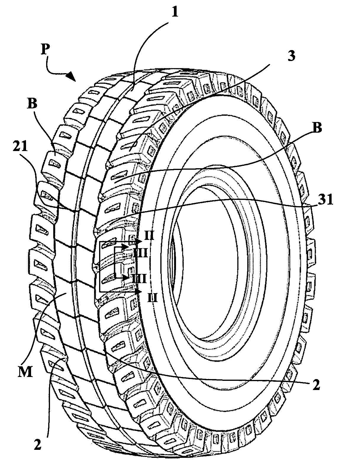
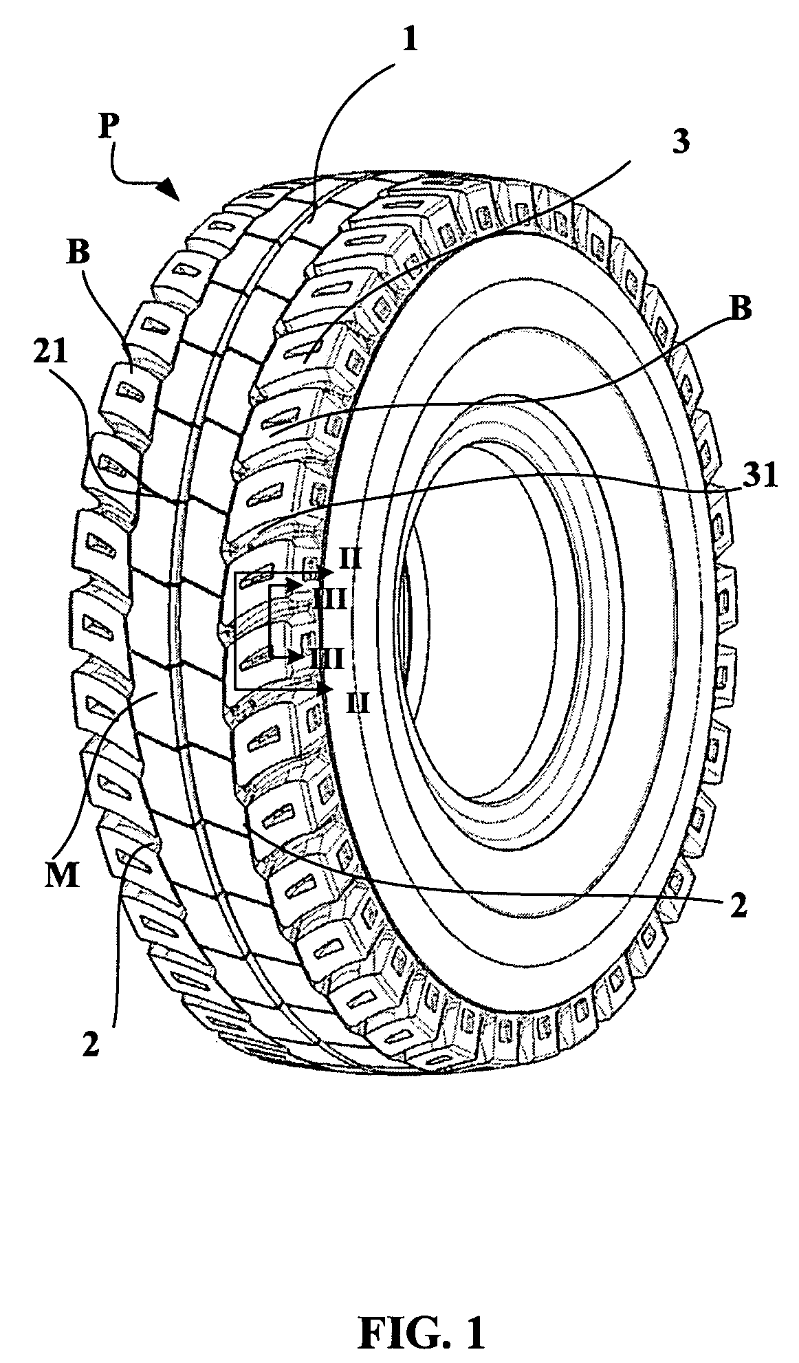
[0039]FIG. 1 shows a perspective view of a tire P according to the invention designed for fitting to a driving axle of a construction vehicle of the dumper type. This tire, of size 40.00 R 57, has a tread 1 of width L (equal to 970 mm) provided with a pattern that divides said tread axially (i.e. in the direction of its width) into three portions:

[0040] a median portion M extending between two grooves 2 of substantially circumferential orientation, this median portion M having a width equal to 410 mm (or 42% of L);

[0041] two portions B forming the edges of the tread on either side of the median portion M.

[0042] The median portion M has a plurality of grooves 21 with substantially transverse orientation; each of these grooves 21 is delimited by rubber faces that in the present case have zero inclination relative to a perpendicular to the rolling surface.

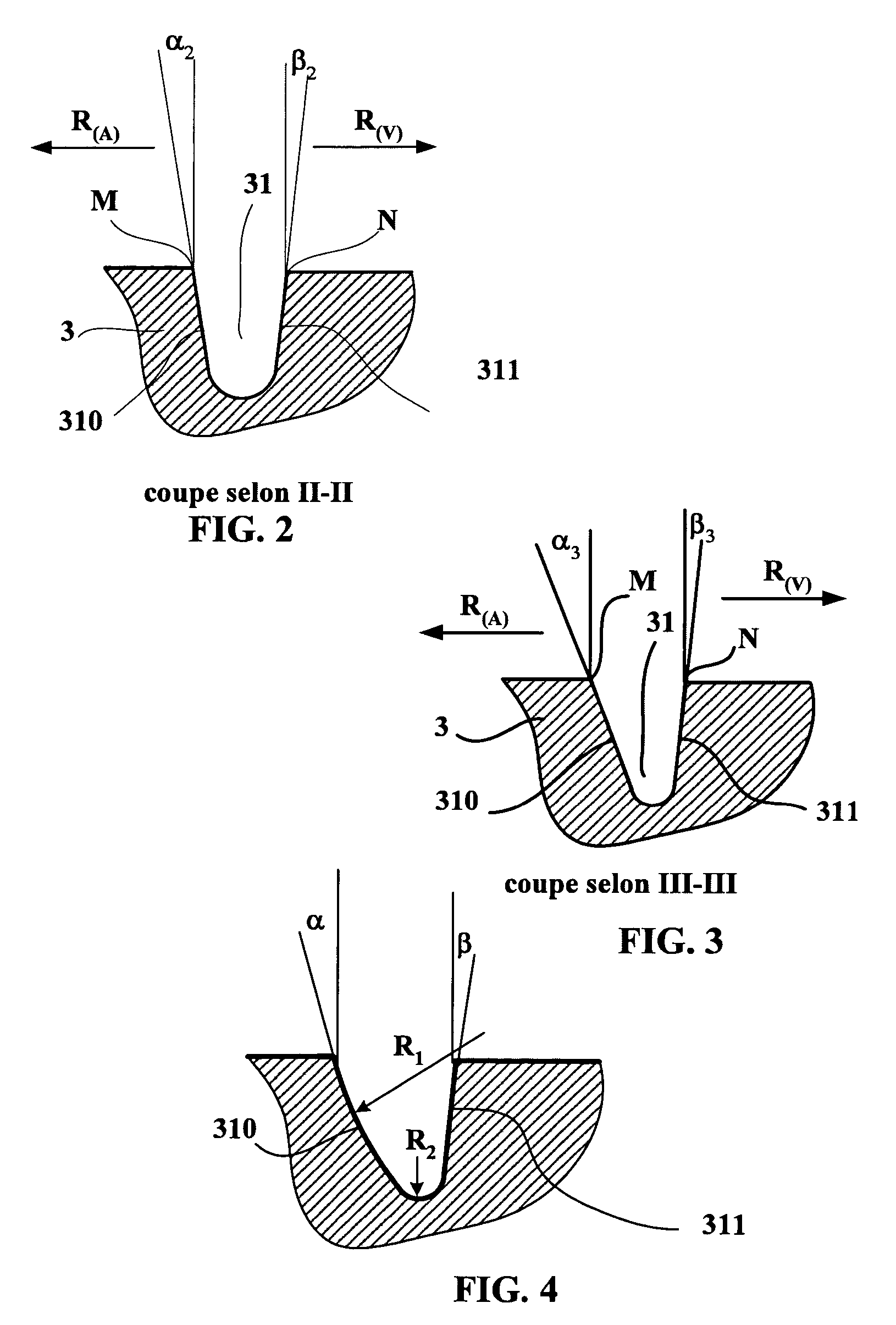
[0043] Each edge portion B is formed of a plurality of rubber blocks 3 spaced apart in the circumferential direction by grooves ...


PUM

PropertyMeasurementUnit
average angleaaaaaaaaaa

Abstract

A method for fitting tires (P) to a driving axle of a vehicle carrying heavy loads, which consists, after having determined the type of journey made by said vehicle, in:
    • when the route is of type A (ascending under load with a driving torque and descending empty with a braking torque), fitting to each driving axle tires such that for each transverse groove (31) in the edge portions (B) of the tread (1), the angle of inclination of the rubber faces (310, 311) delimiting the transverse grooves (31) which first come into ground contact is smaller than the angle of inclination of the rubber face opposite delimiting the same transverse groove, or
    • when the route is of type V (ascending empty and descending under load with a braking torque), fitting to each driving axle tires such that for each transverse groove (31) in the edge portions (B) of the tread, the angle of inclination of the rubber face (310, 311) delimiting said transverse groove which first comes into ground contact is larger than the angle of inclination of the rubber face opposite delimiting the same transverse groove. A tire (P) appropriate for implementing the method described.

Description

FIELD OF INVENTION [0001] The present invention relates to the field of tires for construction machinery and more particularly the tread patterns of such tires; the invention also concerns a method of fitting a dumper vehicle with tires that makes it possible, in accordance with the use of said vehicle, to reduce irregular wear phenomena. BACKGROUND OF INVENTION [0002] Construction vehicles are known which are designed to transport large amounts of ore in mines and which roll in severe conditions, in particular on steeply inclined slopes. Such vehicles, which are referred to as dumpers, are provided with one or more driving axles and a steering axle fitted with appropriately sized tires. It has been found that the wear of such tires is markedly affected by the slippage generated by the longitudinal reaction force exerted by the ground on the tire tread as a result of the torque involved in transporting large loads. [0003] From FR 2382348 a tire of the type fitted to an agricultural ...

Claims


Application Information

Patent Timeline
Patent Type & Authority Applications(United States)
IPC IPC(8): B60C11/13B60C11/03B60C11/04B60C19/00
CPCB60C11/0302B60C11/0316B60C11/032B60C11/13B60C19/001Y10T29/49826Y10S152/904B60C11/0311B60C2011/0313B60C11/1323B60C11/1315B60C2200/065
Inventor VERVAET, PATRICK
Owner MICHELIN RECH & TECH SA
Why Eureka
Try Eureka