
Heat exchange coil cleaning apparatus

a technology for cleaning apparatuses and heat exchange coils, applied in the direction of cleaning equipment, vehicle cleaning, lighting and heating equipment, etc., can solve the problems of affecting the cleaning effect of the unit, the placement of the unit in a poorly ventilated area, and the build-up of debris and dust on the surface of the coil

Inactive Publication Date: 2006-02-23
HEYMAN KEITH A
View PDF7 Cites 29 Cited by
  • Summary
  • Abstract
  • Description
  • Claims
  • Application Information

AI Technical Summary

Benefits of technology

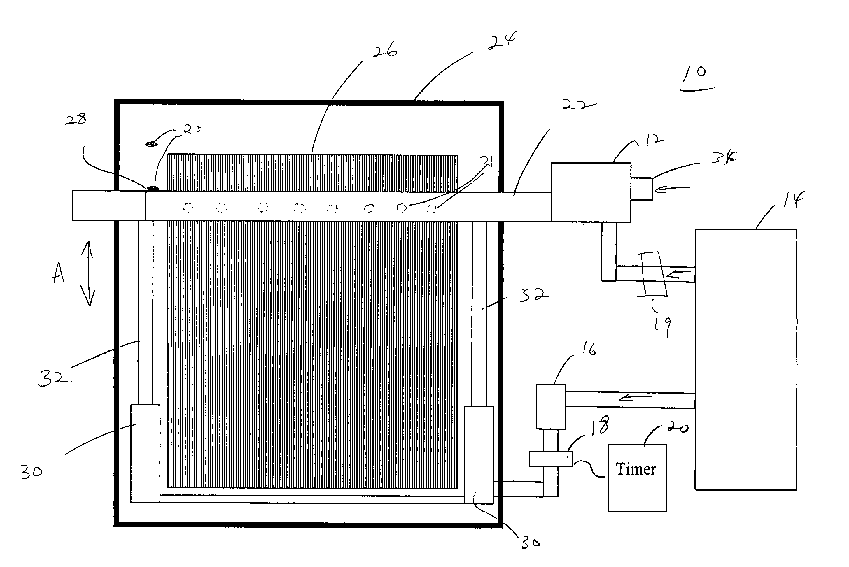
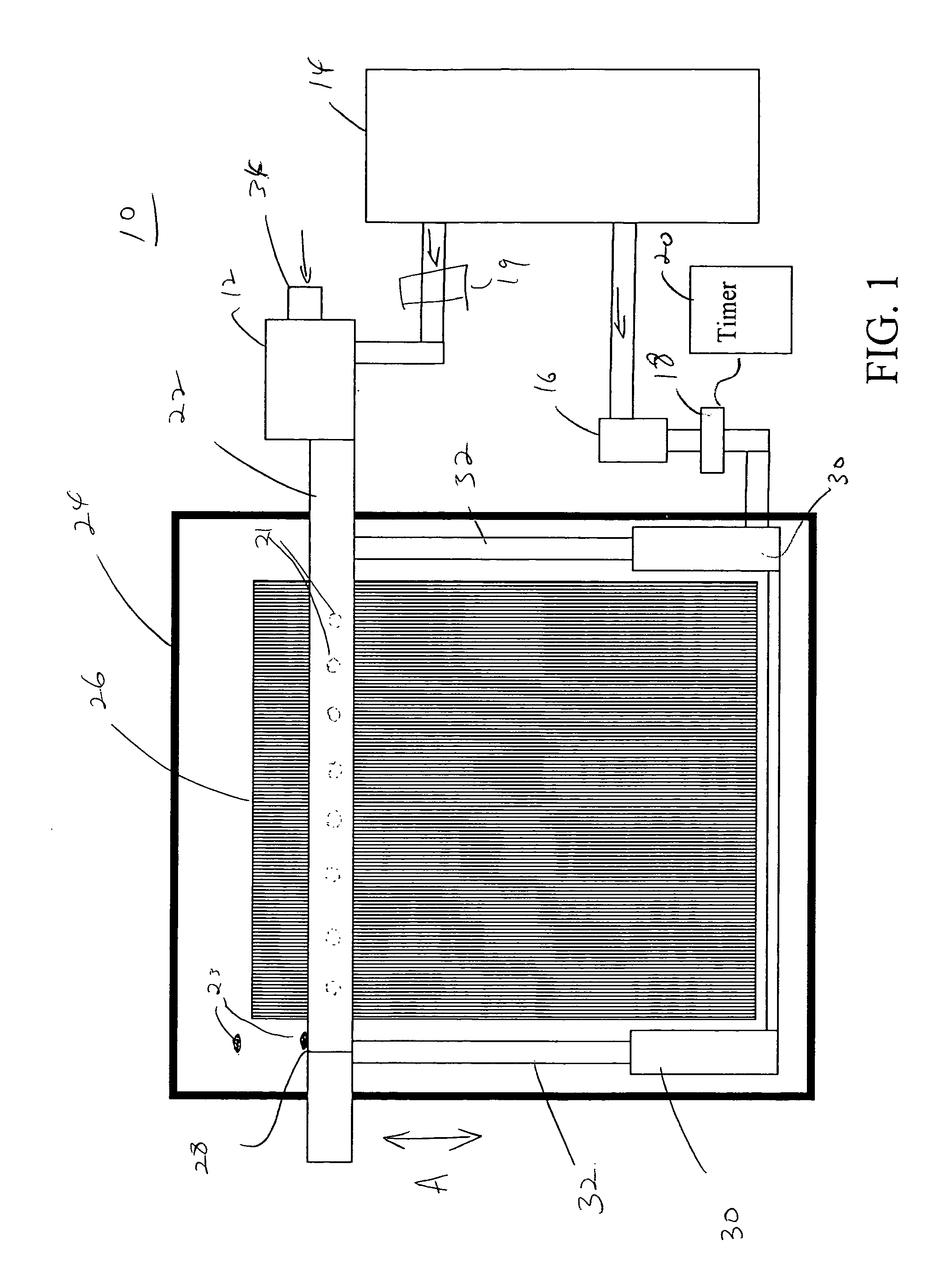
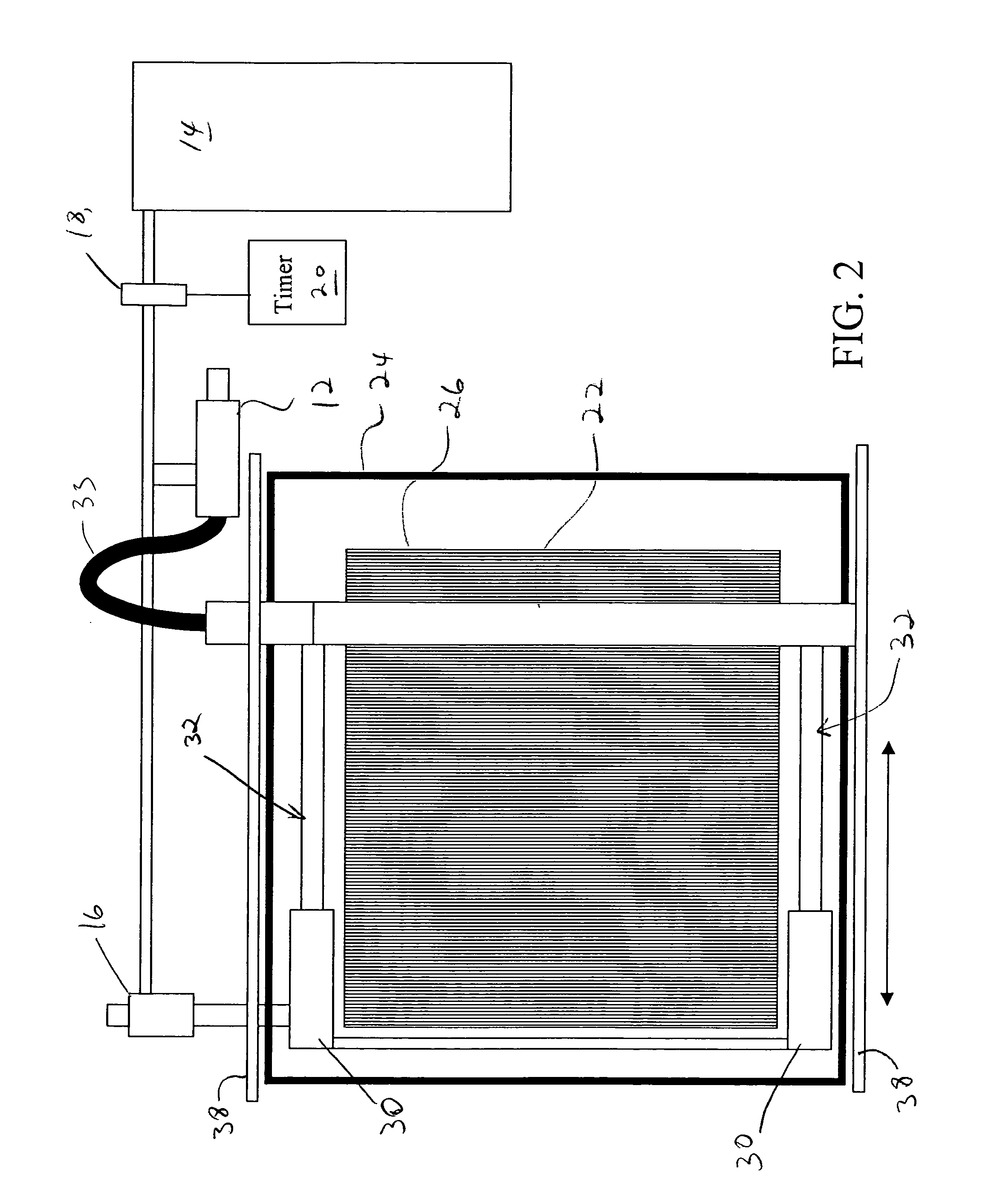
[0011] The collecting device may include a dust collecting material disposed on an opposite side of the coil from the gas-dispensing member. The collecting device may include an irrigation system for maintaining the dust collecting material in a wet state. The collecting device may include a suction tube disposed on an opposite side of the coil from the gas-dispensing member. The collecting device may include orifices directed in a plurality of different directions.

Problems solved by technology

Coils for air conditioning units and refrigeration units or cooling units often collect dust and debris by virtue of their operation.
These types of units often suffer from placement in poorly ventilated areas as well.
As a result, the debris and dust builds up on the surface of the coil.
This build up reduces the efficiency and operation of the air condition and refrigeration units.
This may add a significant expense to the maintenance budget, for say a restaurant of other establishment.

Method used


Image

  • Heat exchange coil cleaning apparatus
  • Heat exchange coil cleaning apparatus
  • Heat exchange coil cleaning apparatus

Examples


Embodiment Construction

[0022] The present invention provides an apparatus for automatically cleaning a coil, such as a condenser coil, for a heat exchange unit. A heat exchange unit may include a cooling unit which in turn is used to refer to refrigerators, refrigeration units, air conditioning units, ice makers, cooling towers, or any other device where a coil or intricate pattern of materials are employed that would benefit from an intermittent cleaning program.

[0023] The present invention provides a tube or other hollow member that carries air or gas therein. The tube delivers the gas onto the coil to clear away dust and debris. The tube is connected to an actuating device, which moves the tube across the coils to deliver the gas at various locations on the coil. The gas is delivered intermittently by employing a timing device. When the timing device triggers the tube, gas in the tube is delivered to clean the coil while the tube moves across the coil. When the tube reaches a given position, the tube ...


PUM


Abstract

A cleaning apparatus for cleaning a heat exchange coil includes a gas-dispensing member having a cavity for carrying a gas and at least one orifice in communication with the cavity. An actuating device which couples to the gas dispensing member and moves the gas dispensing member relative to a coil such that the gas dispensed from the gas dispensing member through the at least one orifice removes dust and debris from the coil. A timer initiates operation of the gas-dispensing member and the actuating device at given time intervals.

Description

BACKGROUND OF THE INVENTION [0001] 1. Field of the Invention [0002] The present invention relates to automated devices, and more particularly to an apparatus for automatically cleaning a coil for air conditioning and refrigeration systems. [0003] 2. Description of the Related Art [0004] Coils for air conditioning units and refrigeration units or cooling units often collect dust and debris by virtue of their operation. These types of units often suffer from placement in poorly ventilated areas as well. As a result, the debris and dust builds up on the surface of the coil. This build up reduces the efficiency and operation of the air condition and refrigeration units. [0005] The cooling units therefore require maintenance to clean them. This maintenance usually requires a heating ventilation and air conditioning (HVAC) professional to make a site visit in order to clean the coils. This may add a significant expense to the maintenance budget, for say a restaurant of other establishment...

Claims


Application Information

Patent Timeline
Patent Type & Authority Applications(United States)
IPC IPC(8): F28G1/12
CPCF28G1/166F25B47/00
Inventor HEYMAN, KEITH A.
Owner HEYMAN KEITH A
Learn More