Transfer unit for transferring glass articles

Inactive Publication Date: 2006-02-23
BOTTERO SPA
View PDF26 Cites 0 Cited by
  • Summary
  • Abstract
  • Description
  • Claims
  • Application Information

AI Technical Summary

Benefits of technology

[0005] It is an object of the present invention to provide a transfer unit designed to provide a straightforward, low-cost solution to the above problems, and which, at the same time, is compact and cheap and easy to produce.

Problems solved by technology

With the increase in the output rate of molding systems, known transfer units of the type described above have proved increasingly unsatisfactory and unreliable.
This is mainly due in part to the presence of pneumatic actuators, the efficiency and controllability of which are severely affected by the thermal conditions in which the transfer unit operates, and in part to the pickup member being connected integrally to the supporting arm, so that it is extremely difficult to set and rapidly correct the pickup positions, the release positions onto the conveyor, and, above all, the travel trajectories of the articles between the pickup and release positions.
This has to be done mainly on account of the different shape and size of the articles for manufacture, and the fact that the articles picked up by the pickup member travel along different trajectories to the conveyor, which are not always the best for ensuring correct transfer of the articles, with the result that numerous damaged articles are rejected at the molding system output.

Method used


Image

  • Transfer unit for transferring glass articles
  • Transfer unit for transferring glass articles
  • Transfer unit for transferring glass articles

Examples


Embodiment Construction

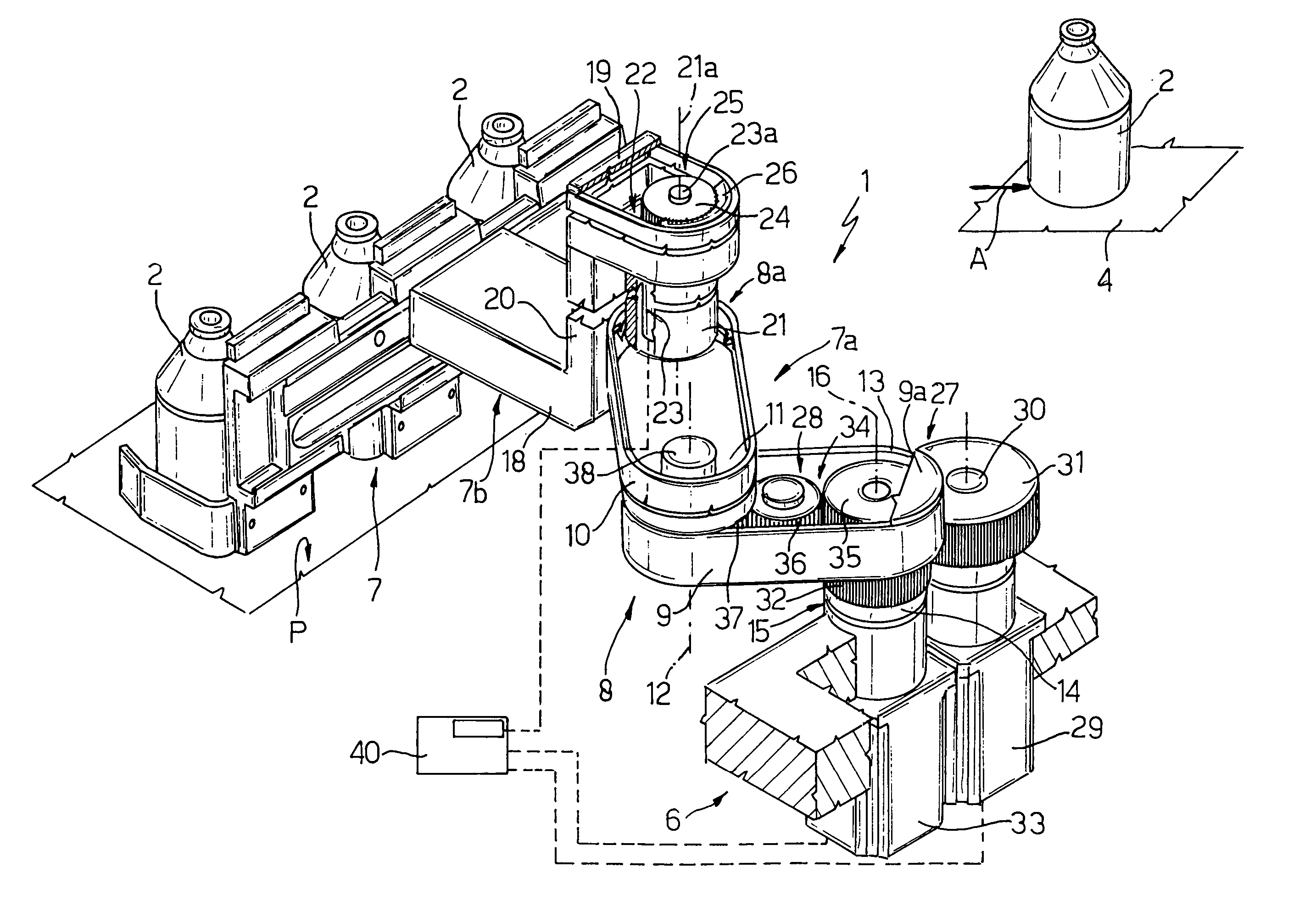
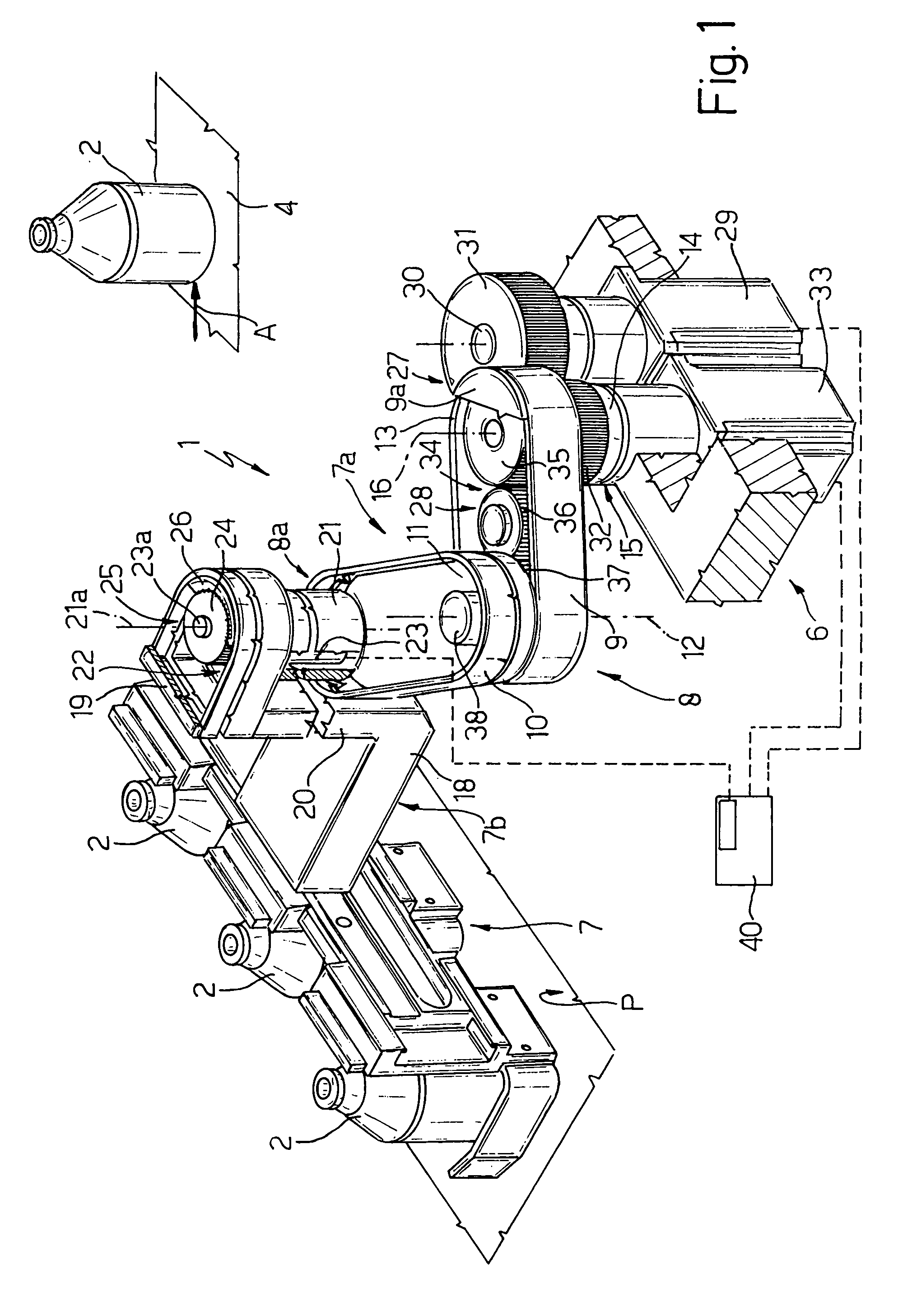
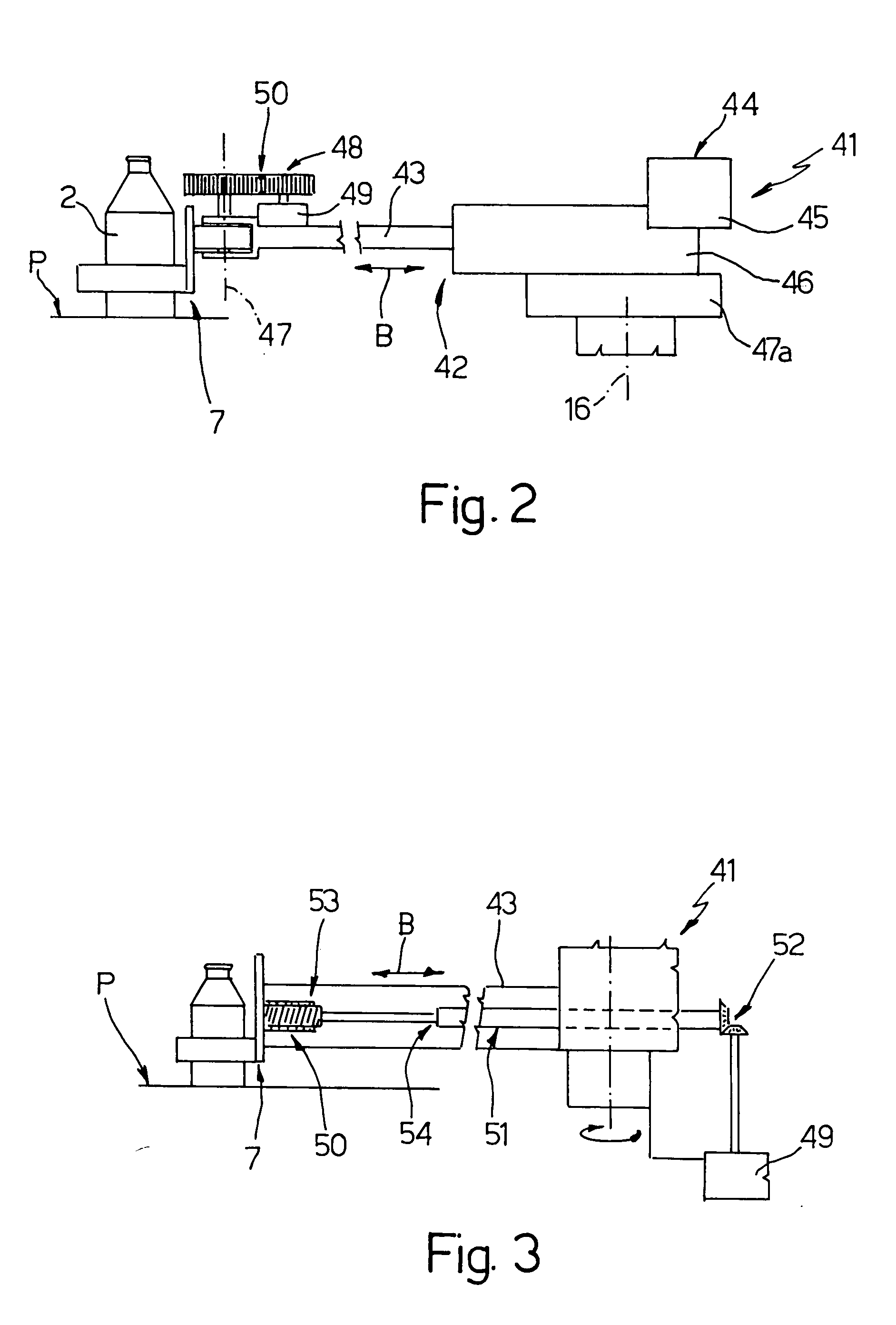
[0012] Number 1 in FIG. 1 indicates as a whole a transfer unit for transferring glass articles 2 from a fixed supporting surface P to a belt conveyor 4 (shown partly) for conveying articles 2 in a direction A to an output of the molding system (not shown) on which articles 2 are molded.

[0013] Transfer unit 1 comprises a fixed supporting frame 6 extending beneath supporting surface P; a known pickup and moving member 7 for engaging articles 2 for transfer; and an actuating device 7a for activating pickup member 7. Device 7a comprises a single articulated arm 8 interposed between pickup member 7 and frame 6, and in turn comprising only two hollow elongated portions 9 and 10. Portions 9 and 10 extend parallel to and over supporting surface P, and are connected to each other by a hinge 11 to rotate, with respect to each other, about a movable hinge axis 12 perpendicular to surface P. With reference to FIG. 1, portion 9 comprises an end portion 13, opposite the end portion hinged to por...


PUM

PropertyMeasurementUnit
Transmissionaaaaaaaaaa

Abstract

A transfer unit for transferring glass articles from a supporting surface to a carry-off conveyor, wherein a pickup member, for engaging the articles for transfer, is hinged to one end of an actuating arm to rotate, with respect to the actuating arm, about a movable hinge axis under the control of a control unit for adjusting the position of the pickup member independently of the position of the actuating arm.

Description

[0001] The present invention relates to a transfer unit for transferring glass articles. BACKGROUND OF THE INVENTION [0002] As is known, hollow glass articles are formed in aligned, adjacent molds, and, once molded, are extracted from the respective molds and placed on a supporting surface, from which they are subsequently transferred onto a linear conveyor which feeds them successively to an output of the system. [0003] The glass articles are transferred from the supporting surface to the linear conveyor by means of transfer units, each of which comprises a pickup member for engaging one or more articles to be transferred; a movable supporting arm fitted integrally with the pickup member; a pneumatic linear actuator for moving the supporting arm and the pickup member horizontally to and from the glass articles; and an angular actuator, normally electric, for rotating the supporting arm, about a fixed vertical hinge axis, between a pickup position, to pick the articles off the suppo...

Claims


Application Information

Patent Timeline
IPC IPC(8): B65G25/00
CPCB65G47/82C03B9/453B65G2201/0247B65G47/904
Inventor BORSARELLI, GIANCLAUDIOGIANTI, PAOLOSESIA, CARLOVIADA, BRUNO
Owner BOTTERO SPA
Why Eureka
Try Eureka