Power window system

Active Publication Date: 2006-02-23
YAZAKI CORP
View PDF13 Cites 11 Cited by
  • Summary
  • Abstract
  • Description
  • Claims
  • Application Information

AI Technical Summary

Benefits of technology

[0012] In view of the aforementioned situation, an object of the invention is to provide a practical power window system that can surel

Problems solved by technology

The device detects an over current flowing in an electric motor moving the w

Method used


Image

  • Power window system
  • Power window system
  • Power window system

Examples


Example

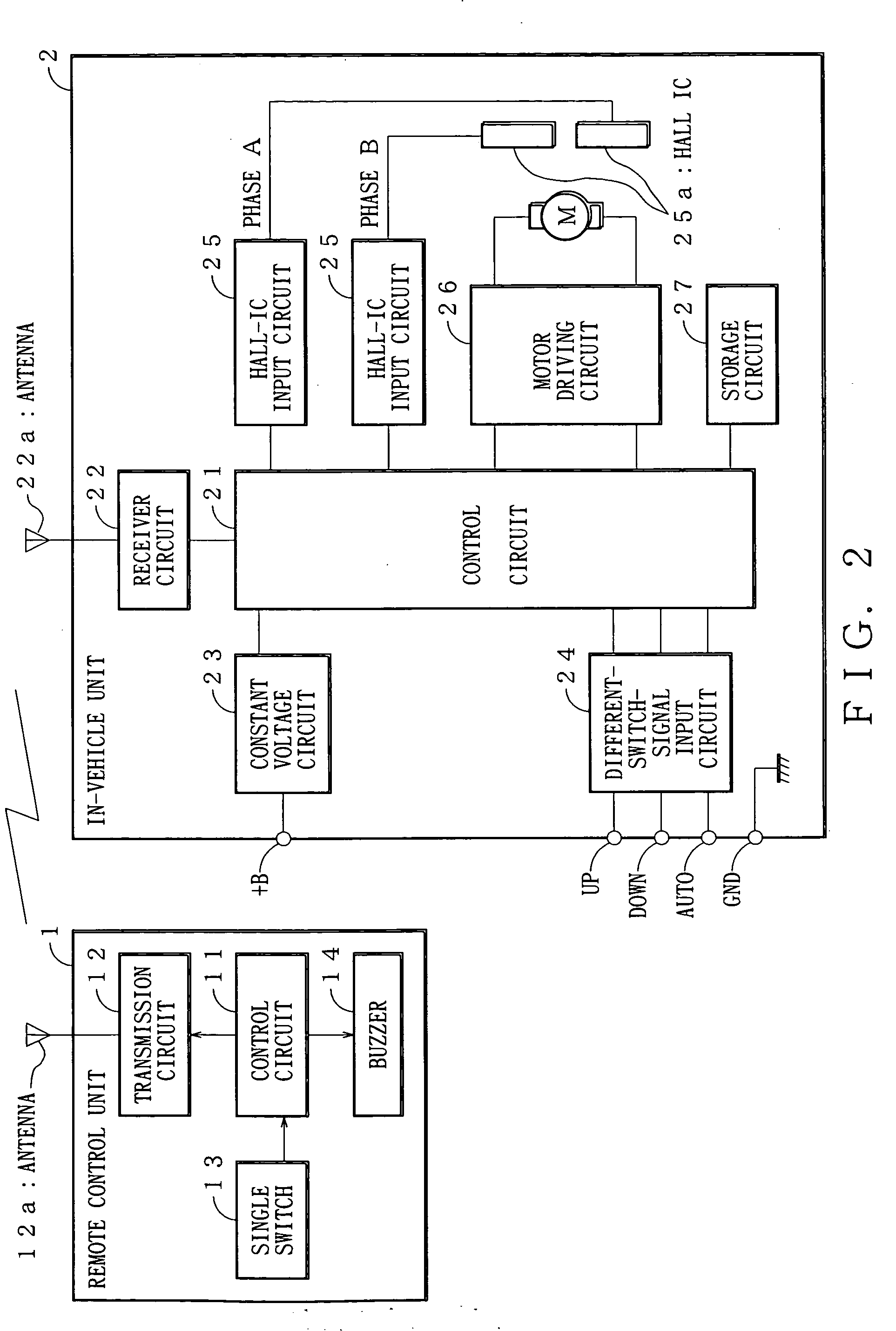
[0027] Referring to the accompanied drawings, embodiments of the present invention will be discussed hereinafter. FIG. 2 is a block diagram showing a hardware configuration of a power window system of an embodiment according to the present invention.

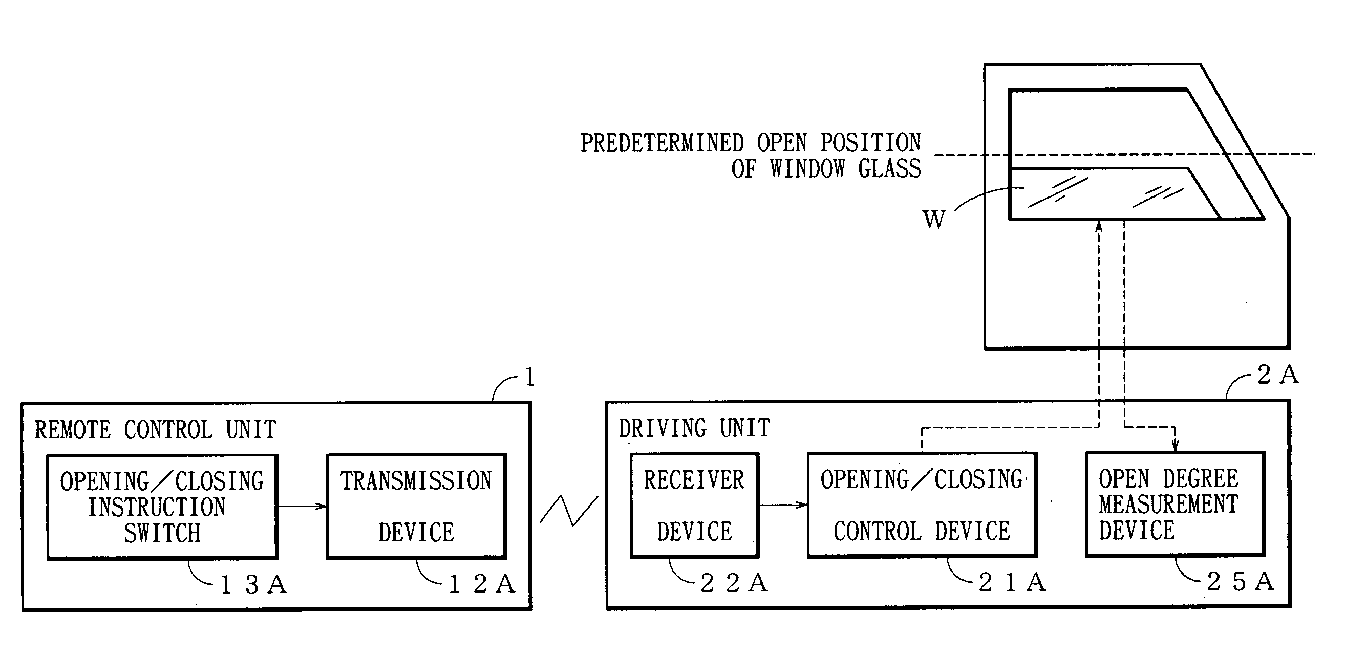
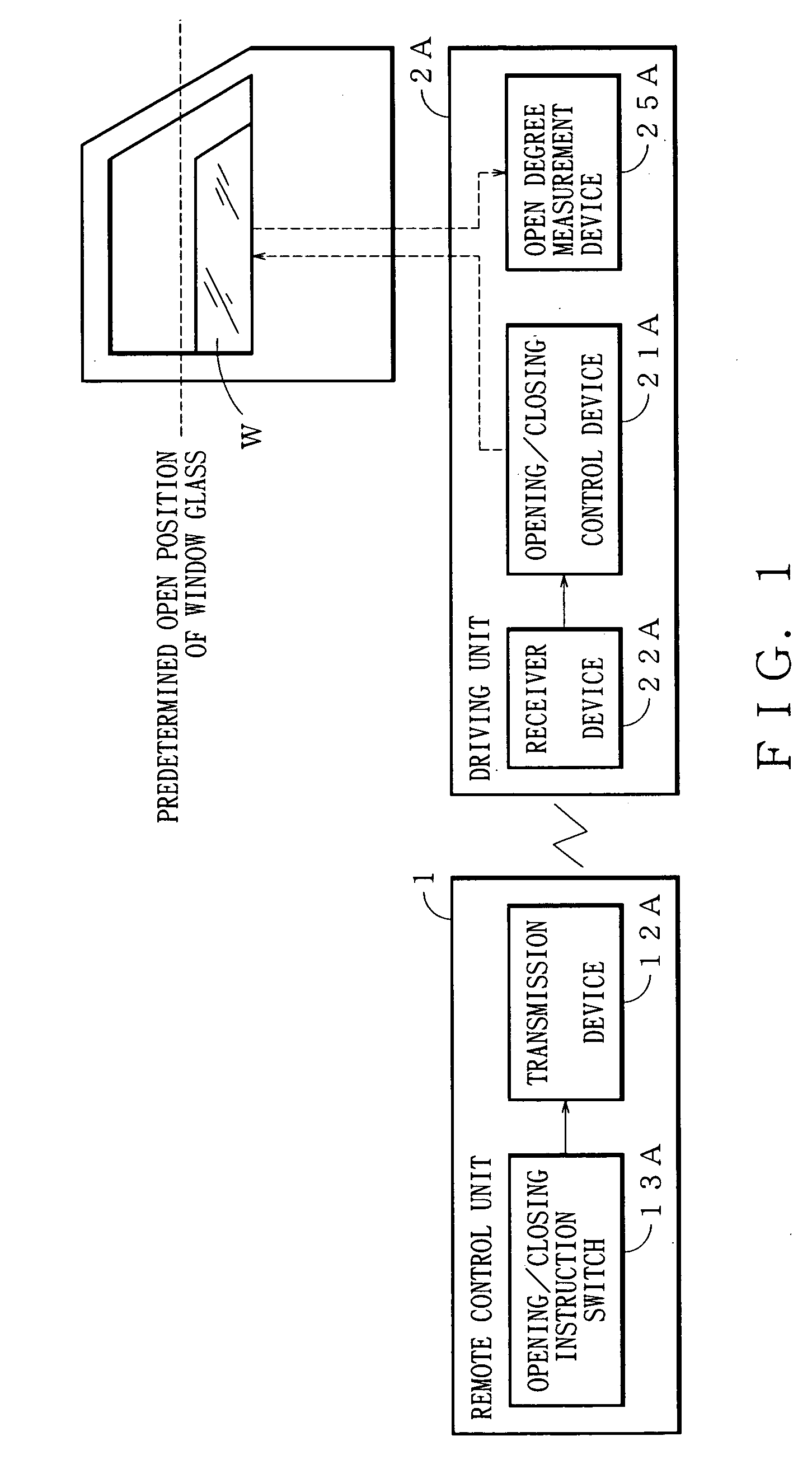
[0028] The power window system, for example, operates to open and close a side window glass of a motor vehicle. As shown in FIG. 2, the power window system has a remote control unit 1 and an in-vehicle unit 2. In this discussion, “up” means a closing movement of the window glass and “down” means an opening movement of the window glass.

[0029] As shown in FIG. 2, the remote control unit 1 has a control circuit 11, a transmission circuit 12 corresponding to a radio device of claims, a single switch 13 corresponding to an opening / closing instruction switch of the claims, and a buzzer 14. The remote control unit 1 may have a profile like a remote unit including a car key for a well-known remote entry device. The control circuit 11 is a micr...


PUM


Abstract

The power window system moves a window glass in opening and closing directions in response to operation of an opening and closing instruction switch. The power window system includes a measurement device for obtaining an open degree of the window glass and a control device for controlling movement of the window glass in response to operation of the switch. The control device moves the window glass in the closing direction when an open degree obtained by the measurement device is not less than a predetermined degree and in the opening direction when the open degree is less than the predetermined degree.

Description

BACKGROUND OF THE INVENTION [0001] 1. Field of the Invention [0002] The present invention relates to a power window system, more particular to a power window system that moves a window glass in opening and closing directions in response to operation of a single switch. [0003] 2. Related Art [0004] Recently, a power window system has been proposed, in which a remote control single switch operates a window glass to move in opening and closing directions. For example, this type power window system opens and closes a side window glass of a motor vehicle. The power window system has a remote control unit to input instructions for opening and closing the window glass and an in-vehicle-mounted unit for moving the window glass in response to the instructions of the remote control unit. [0005]FIG. 4 is a flowchart showing process steps of the in-vehicle unit with regard to the power window system. Step S91 of FIG. 4 determines whether a power window (PW) operation signal has been input. When...

Claims


Application Information

Patent Timeline
IPC IPC(8): H02P3/00H02P1/00B60J1/17E05F15/665E05F15/689E05F15/75E05F15/77
CPCE05Y2900/55H02H7/0816E05F15/695E05F15/41H02H7/0851
Inventor NAKAGAWA, SATOSHIMAEJIMA, YOSHIMITSUMOCHIZUKI, YASUYUKIIWASAKI, KATSUYUKIYAMAMOTO, SUSUMU
Owner YAZAKI CORP
Why Eureka
Try Eureka