Method for imaging subterranean formations

a subterranean formation and imaging technology, applied in seismology for waterlogging, instruments, using reradiation, etc., can solve the problems of inability to determine the location of anomalies with sufficient depth or speed, inability to detect anomalies at a sufficient distance ahead of a bit or bottom hole assembly, and limited depth of investigation facilitated by tools

Inactive Publication Date: 2006-02-23
SHELL OIL CO
View PDF22 Cites 94 Cited by
  • Summary
  • Abstract
  • Description
  • Claims
  • Application Information

AI Technical Summary

Benefits of technology

[0034] The again monitored one of apparent conductivity and apparent resistivity can be plotted in the same plot as the plot wherein the one of apparent conductivity and apparent resistivity was originally plotted. The creating

Problems solved by technology

While currently available techniques are capable of detecting the presence of an anomaly, they are not capable of determining the location of the anomaly with sufficient depth or speed, they are not capable of detecting an anomaly at a sufficient distance ahead of a bit or bottom hole assembly.
As set forth above, the depth of investigation facilitated by the tool is limited.
However, longer tools generally result in poor spatial resolution.
However, while Payton discloses a transient EM method enabling detection of an anomaly, it does not pr

Method used


Image

  • Method for imaging subterranean formations
  • Method for imaging subterranean formations
  • Method for imaging subterranean formations

Examples


Embodiment Construction

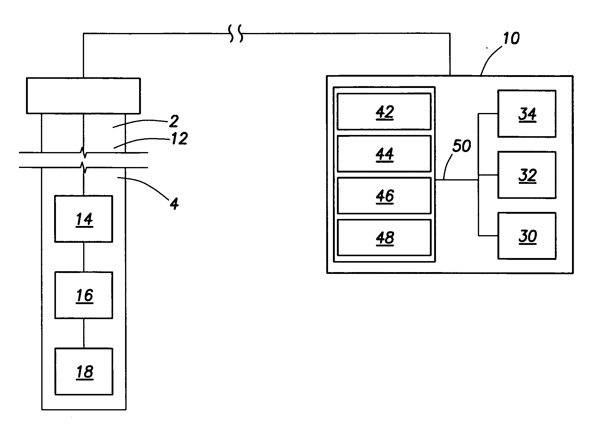
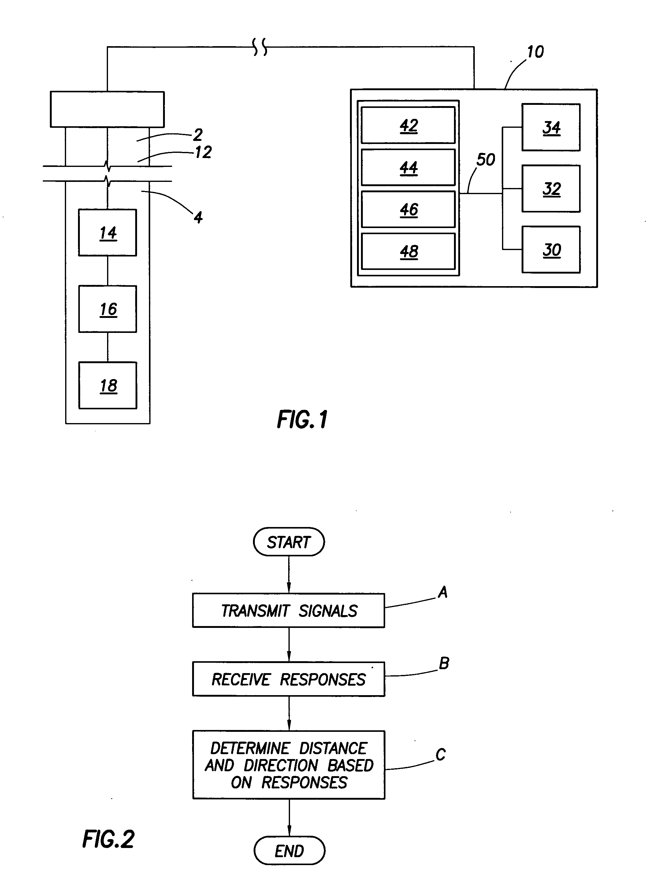
[0102] Embodiments of the invention relate to a system and method for determining distance and direction to an anomaly in a formation within a wellbore. Both frequency domain excitation and time domain excitation have been used to excite electromagnetic fields for use in anomaly detection. In frequency domain excitation, a device transmits a continuous wave of a fixed or mixed frequency and measures responses at the same band of frequencies. In time domain excitation, a device transmits a square wave signal, triangular wave signal, pulsed signal or pseudo-random binary sequence as a source and measures the broadband earth response. Sudden changes in transmitter current cause signals to appear at a receiver caused by induction currents in the formation. The signals that appear at the receiver are called transient responses because the receiver signals start at a first value and then decay or increase with time to a constant level. The technique disclosed herein implements the time do...


PUM


Abstract

A method of imaging a subterranean formation traversed by a wellbore using a tool comprising a transmitter for transmitting electromagnetic signals through the formation and a receiver for detecting response signals. The tool is brought to a first position inside the wellbore, and the transmitter is energized to propagate an electromagnetic signal into the formation. A response signal that has propagated through the formation is detected. A derived quantity for the formation based on the detected response signal for the formation is calculated, and plotted against time. The tool may be moved to at least one other position within the wellbore where the procedure may be repeated to create an image of the formation within the subterranean formation based on the plots.

Description

CROSS-REFERENCE TO RELATED APPLICATIONS [0001] The present application is a continuation-in-part application of U.S. application Ser. No. 10 / 897,585, filed on Jul. 23, 2004, which is a continuation-in-part application of U.S. application Ser. No. 10 / 701,735 filed on Nov. 5, 2003, each of which are incorporated herein by reference. In addition, applicants claim priority based on U.S. provisional application Ser. No. 60 / 639,941, filed on Dec. 29, 2004.FIELD OF THE INVENTION [0002] In one aspect the present invention relates to a method for imaging a subterranean formation traversed by a wellbore. In another aspect, the present invention relates to a method for determining at least first and second distances from a device to at least a first layer and a second layer in a formation. [0003] In an embodiment, the invention relates to a method for locating an anomaly and in particular to finding the location of a resistive or conductive anomaly in a formation surrounding a borehole in dril...

Claims


Application Information

Patent Timeline
IPC IPC(8): G01V3/18
CPCG01V3/38G01V3/28
Inventor OSTERMEIER, RICHARD MARTINHAGIWARA, TERUHIKOBANNING, ERIK JAN
Owner SHELL OIL CO
Why Eureka
Try Eureka