Wireless messenger system

a wireless messenger and messenger technology, applied in the field of security systems, can solve the problems of not being able to reprogram the electronic lock, the resident of the room cannot access the room, etc., and achieve the effect of preserving battery consumption and tracking usag

Inactive Publication Date: 2006-02-23
COMPIZED SECURITY SYST
View PDF6 Cites 27 Cited by
  • Summary
  • Abstract
  • Description
  • Claims
  • Application Information

AI Technical Summary

Benefits of technology

[0012] Accordingly, the inventive method provides for interrogation and communication between electronic locks that conserves battery consumption and tracks usage. T

Problems solved by technology

Previous versions of programmed keys may not actuate the lock, preventing the old resident of the room from accessing the room.
These situations may arise when an electronic key is l

Method used


Image

  • Wireless messenger system
  • Wireless messenger system
  • Wireless messenger system

Examples


Embodiment Construction

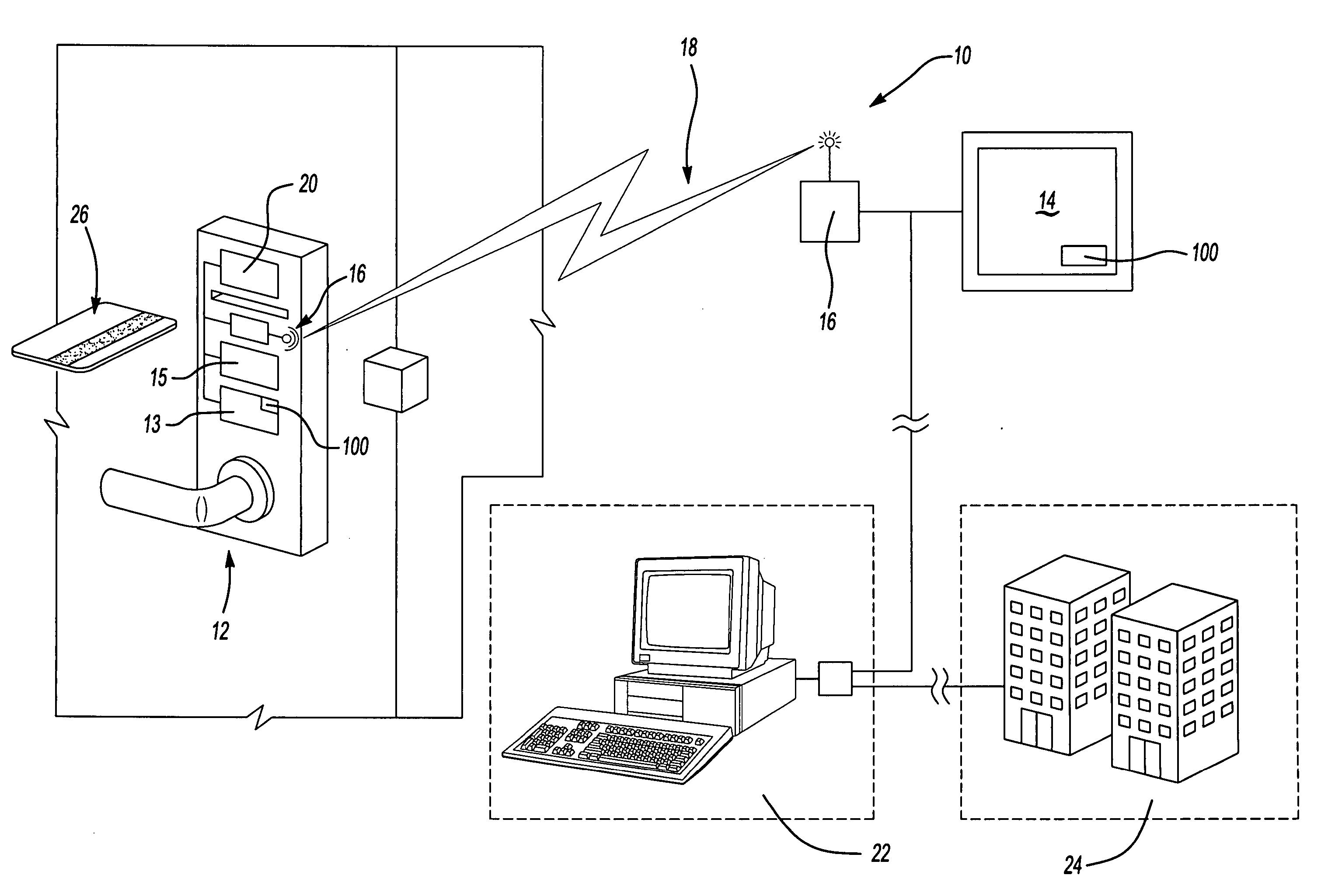
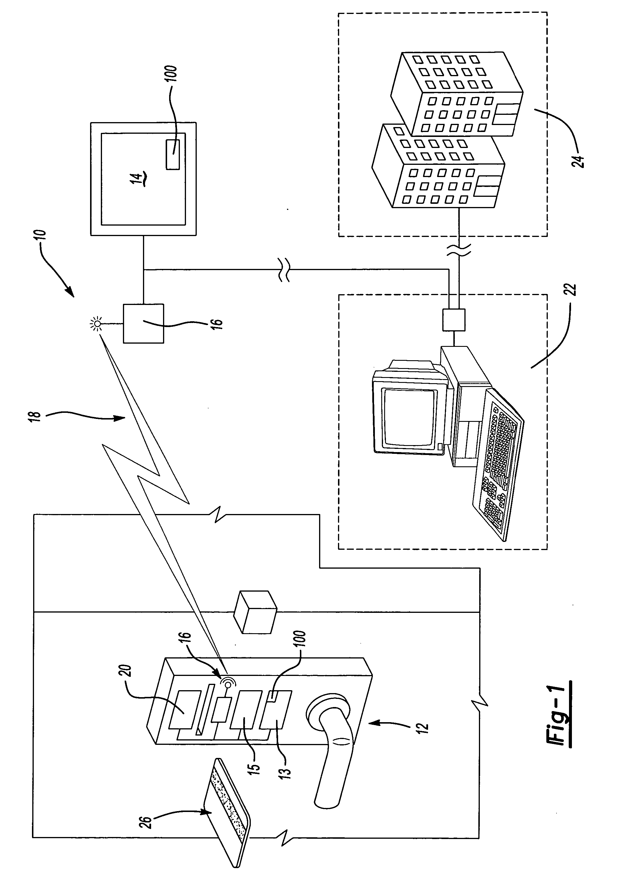
[0018]FIG. 1 is a general schematic view of a security system 10 for a multi-room facility, schematically shown at 24, that utilizes radio frequency signals to communicate from multiple electronic lock stations 12 corresponding to each room of the facility 24. The system 10 includes the electronic lock stations 12 along with several access point hubs 14. Communications between the access point hub 14 and the lock stations 12 take place via a two-way radio frequency signal 18. The lock station 12 and the access point hub 14 both include a transceiver 16. The transceivers 16 send and accept the radio frequency signals 18 that are sent from either the lock stations 12 or the access point hubs 14.

[0019] The lock station 12 and the access point hub 14 communicate using a frequency hopping protocol to provide consistent and reliable communication while conserving battery power at the lock stations 12. The radio frequency signal 18 is sent according to this invention to communicate betwee...


PUM


Abstract

A method of communicating between electronic door locks, access point hubs and a central controller includes the steps of transmitting a probe signal from a central controller, or access point hub receiver to the electric door lock in several different frequencies. Transmission between the locks stations and the access point hub are then synchronized to accommodate multiple lock stations and to prevent overlapping transmissions.

Description

CROSS REFERENCE TO RELATED APPLICATION [0001] The application claims priority to U.S. Provisional Application No. 60 / 602,409 which was filed on Aug. 18, 2004.BACKGROUND OF THE INVENTION [0002] The present invention relates to a security system, and more particularly to a method of communicating information to electronic door locks within a multi-room facility. [0003] Multi-room facilities typically control access to rooms in the facility with electronic door locks. Electronic keys to actuate the electronic door locks provide access to the rooms in the facility. When access to a room is desired, an electronic key is programmed to actuate the electronic door lock of that room. [0004] Programming the electronic key to the electronic lock usually requires direct access to the electronic lock. For instance, when a new resident of the room replaces a previous resident of the room the new resident is given a newly programmed key. The new resident proceeds to the room and inserts the newly ...

Claims


Application Information

Patent Timeline
IPC IPC(8): G05B19/00H04B1/713
CPCG07C9/00G07C9/00103H04B1/713G07C2209/06G07C2209/61G07C9/00904G07C9/27
Inventor KHALIL, MOHAMAD A.
Owner COMPIZED SECURITY SYST
Why Eureka
Try Eureka