Liquid crystal display

a technology of liquid crystal display and liquid crystal, applied in the field of liquid crystal display, can solve the problems of inability to form color filters with different thicknesses on the opposite substrate for different areas, drop in luminance, undesired reduction of display luminance, etc., and achieve excellent visibility.

Inactive Publication Date: 2006-02-23
NEC LCD TECH CORP
View PDF2 Cites 3 Cited by
  • Summary
  • Abstract
  • Description
  • Claims
  • Application Information

AI Technical Summary

Benefits of technology

[0014] Accordingly, it is an object of the invention to provide a semi-transmission type liquid crystal display which has an excellent visibility in reflection mode as well as in transmission mode.

Problems solved by technology

In case where the areas of the undulations are reduced to form the transmission areas so that the liquid crystal display is used as a reflection type liquid crystal display with the backlight turned off, there arises a problem that the luminance drops.
Because the projections have isolated circular shapes, however, the reflector simultaneously reflects incident lights from all the directions and has no directivity, the display luminance is undesirably reduced.
As the reflector described in Japanese Patent Laid-Open No. 2001-75091 has transmission areas and reflection areas mixed in pixels, however, it is difficult to form color filters with different thicknesses on the opposite substrate for different areas.
This makes it impossible to adjust the thicknesses of the color filters area by area.
This changes the hue in transmission mode and reflection mode, so that the reduction in luminance and the change in hue lower the visibility.

Method used


Image

  • Liquid crystal display
  • Liquid crystal display
  • Liquid crystal display

Examples


first embodiment

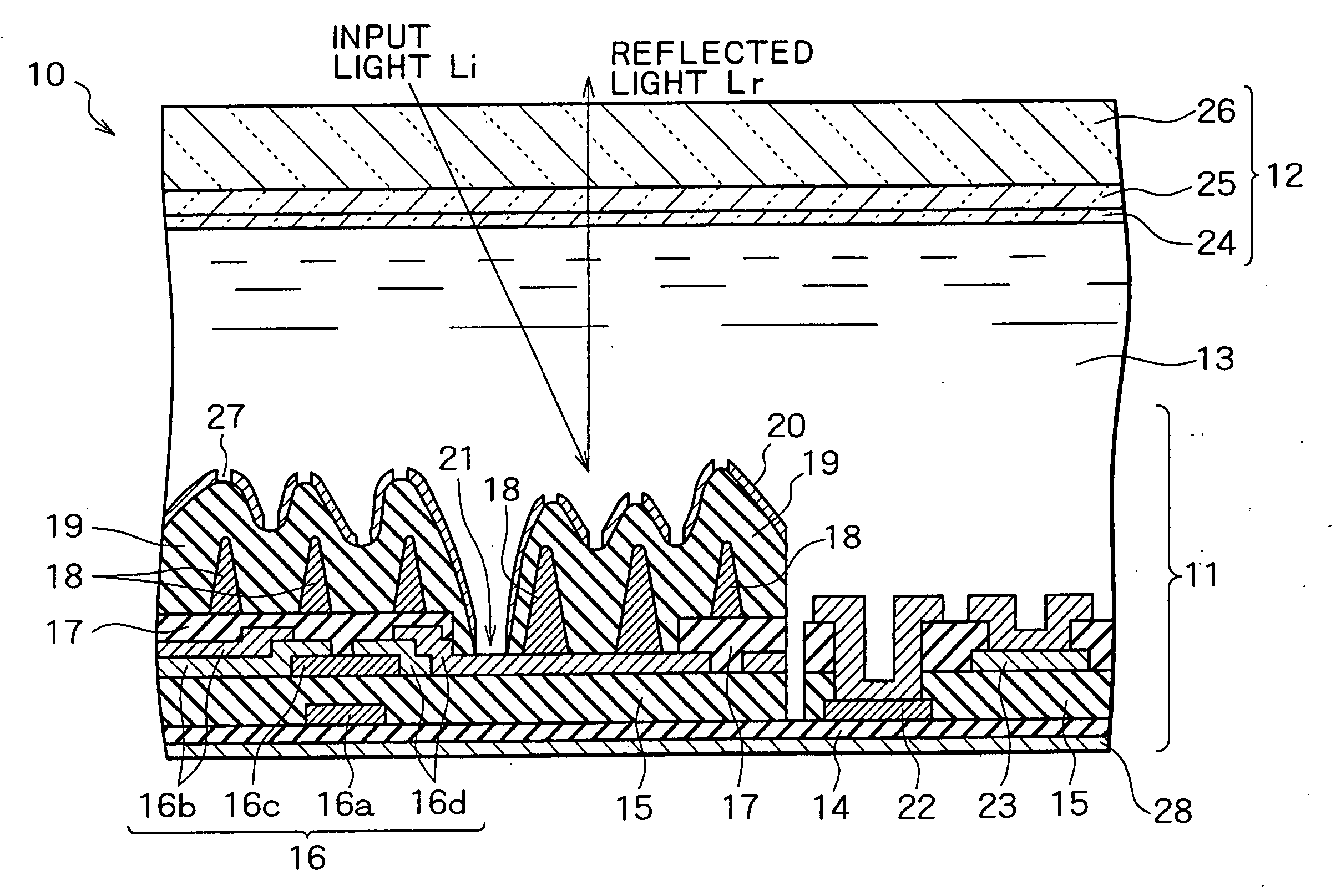
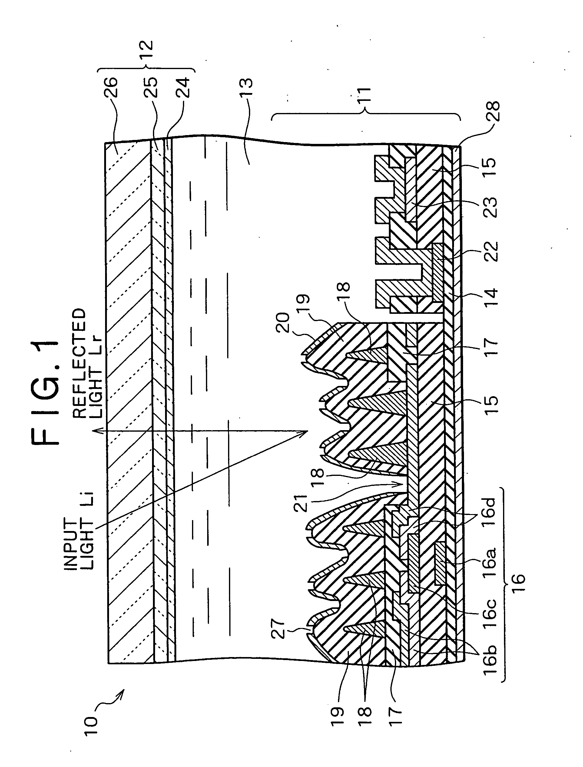
[0094] Embodiments of the invention will be described below with reference to the accompanying drawings. FIG. 1 is a partial cross-sectional view of a semi-transmission type liquid crystal display according to the present invention. As shown in FIG. 1, a semi-transmission type liquid crystal display 10 has, inside, a lower substrate 11, an opposite substrate 12 so arranged as to face the lower substrate 11 and a liquid crystal layer 13 sandwiched between the lower substrate 11 and the opposite substrate 12.

[0095] The semi-transmission type liquid crystal display 10 employs an active matrix system which has, for example, thin film transistors (TFTs) provided as switching elements pixel by pixel.

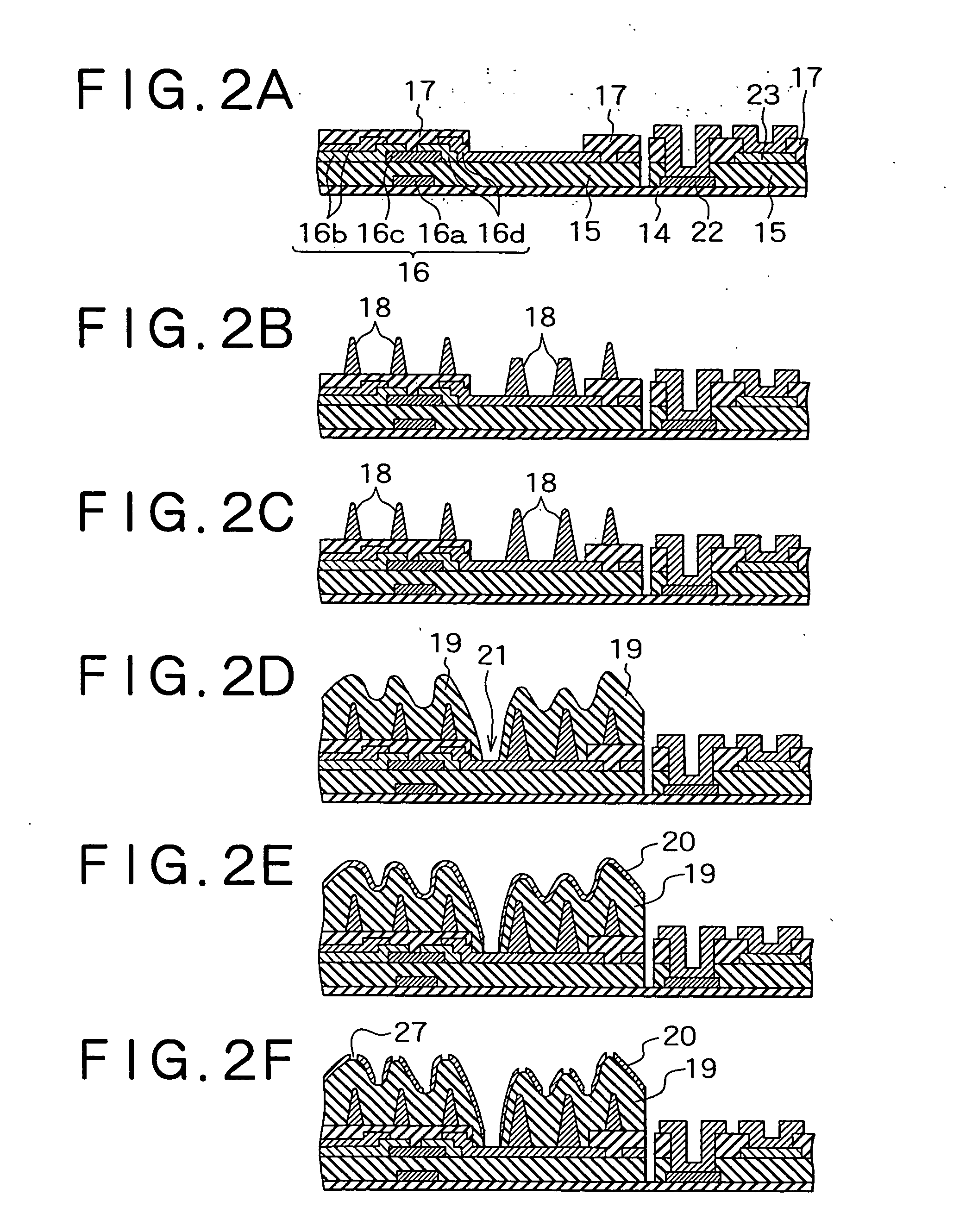
[0096] The lower substrate 11 has an insulative substrate 14, an insulating protection film 15, TFTs 16, an insulating layer 17, projection patterns 18, a second insulating layer 19 and a reflection electrode 20. The insulating protection film 15 is deposited on the insulative substrate 14 an...

second embodiment

[0131]FIG. 14 is a partial cross-sectional view of a semi-transmission type liquid crystal display according to the invention. As shown in FIG. 14, a semi-transmission type liquid crystal display 10 has, inside, a lower substrate 11, an opposite substrate 12 so arranged as to face the lower substrate 11 and a liquid crystal layer 13 sandwiched between the lower substrate 11 and the opposite substrate 12.

[0132] The lower substrate 11 has an insulative substrate 14, an insulating protection film 15, TFTs 16, an insulating layer 17, projection patterns 18, a second insulating layer 19, a reflection electrode 20 and a transparent electrode 31. The insulating protection film 15 is deposited on the insulative substrate 14 and the TFTs 16 are formed on the insulating protection film 15. Each TFT 16 has a gate electrode 16a on the insulative substrate 14, a drain electrode 16b, a semiconductor layer 16c and a source electrode 16d, the last three electrodes lying on the insulating protection...

third embodiment

[0159] In the display of the reflection mode, input light from the opposite substrate 12 passes the color filter 25 provided on the opposite substrate 12 twice until it becomes output light, In the display of the transmission mode, the light from the backlight 28 passes the color filter 25 provided on the lower substrate 11 and the color filter 25 provided on the opposite substrate 12 until it becomes output light. In reflection and transmission modes, the light passes the color filter twice, so that the liquid crystal display of the third embodiment can make the color expression identical in both modes. It is also possible to determine the balance of colors displayed independently between the transmission mode and reflection mode.

[0160] An ECB (Electrically Controlled Birefringence) type, homogeneous type, homeotropic type, TN type, HAN type, OCB type or the like is used for the liquid crystal layers 13 according to the first embodiment and the second embodiment.

[0161]FIGS. 18A th...


PUM

PropertyMeasurementUnit
tilt angleaaaaaaaaaa
polar angleaaaaaaaaaa

Abstract

A reflection electrode has an undulated shape and whose normal direction is distributed unevenly to a specific azimuth angle and whose reflection light intensity depends on said azimuth angle. Openings are formed in that area of the reflection electrode which has a tilt angle of 0 degree to 2 degrees and / or a tilt angle of 10 degrees or higher. The retardation of a liquid crystal layer is changed by making the liquid crystal molecular alignment mode different between the openings and the reflection electrode, so that the intensity of output light is increased in reflection mode as well as in transmission mode. The balance of colors displayed in transmission mode is determined by determining the area of the openings in pixels of each color, and the color temperature is set higher in transmission mode than in reflection mode. This provides a semi-transmission type liquid crystal display which has an excellent visibility in reflection mode as well as in transmission mode.

Description

BACKGROUND OF THE INVENTION [0001] 1. Field of the Invention [0002] The present invention relates to a liquid crystal display, and, more particularly, to a semi-transmission type liquid crystal display which reflects incident light coming from outside to provide a display light source and transmits light from a light source at the back. [0003] 2. Description of the Related Art [0004] There is a reflection type liquid crystal display (LCD) known which has a reflector inside and reflects incident external light by the reflector to provide a display light source, thereby eliminating the need for a backlight as a light source and a transmission type liquid crystal display equipped with a backlight as a light source. [0005] As the reflection type liquid crystal display can be designed with lower power consumption, thinner and lighter than the transmission type liquid crystal display, it is mainly used for a portable terminal. This is because as light input from outside is reflected at th...

Claims


Application Information

Patent Timeline
Patent Type & Authority Applications(United States)
IPC IPC(8): G02F1/1335G02B5/02G02B5/08G02B5/30G02F1/1343
CPCG02F1/133555G02F1/1343
Inventor IKENO, HIDENORISUZUKI, MASAYOSHIMURAYAMA, YOUICHISAKAMOTO, MICHIAKIMATSUNO, FUMIHIKOKIKKAWA, HIRONORIYAMAGUCHI, YUICHI
Owner NEC LCD TECH CORP
Why Eureka
Try Eureka