
Sunlight measuring device

a technology of sunlight and measuring device, which is applied in the field of sunlight measuring device, can solve the problems of difficult evaluation form for gardeners, lack of tools to accurately measure the amount of accumulated sunlight at the site, and other devices are complicated to use, so as to achieve accurate measurement

Inactive Publication Date: 2006-02-23
BAR DEV
View PDF16 Cites 24 Cited by
  • Summary
  • Abstract
  • Description
  • Claims
  • Application Information

AI Technical Summary

Benefits of technology

[0008] For reasons cited above, it is an object of this invention to provide a device that accurately measures the amount of accumulated light that falls at a particular site and provides information on the general light condition at that site over a 24 hour period of time. It is a further object to provide such a device that displays the information in terms that relate directly to the sunlight tolerance recommendations provided by nurseries and garden centers on most plant labels.

Problems solved by technology

Gardeners and landscapers are well aware of the need to match the light requirements of a plant with the light condition of specific planting site, but often lack the necessary tools to accurately measure accumulated sunlight conditions at the site over a period of time.
Other devices measure accumulated sunlight over a period of time, but provide the information in a form that is difficult for gardeners to evaluate, such as in sols / h and total sols per selected period of time.
Still other devices are complicated to use because they require some data input effort on the part of the user.

Method used


Image

  • Sunlight measuring device
  • Sunlight measuring device
  • Sunlight measuring device

Examples


Embodiment Construction

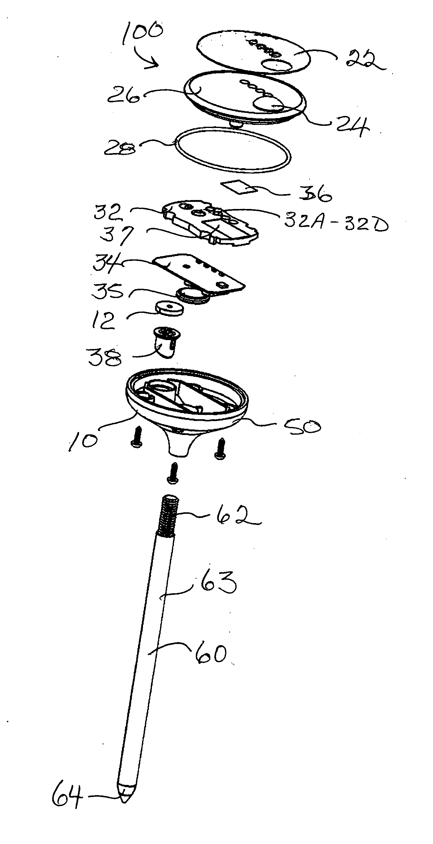
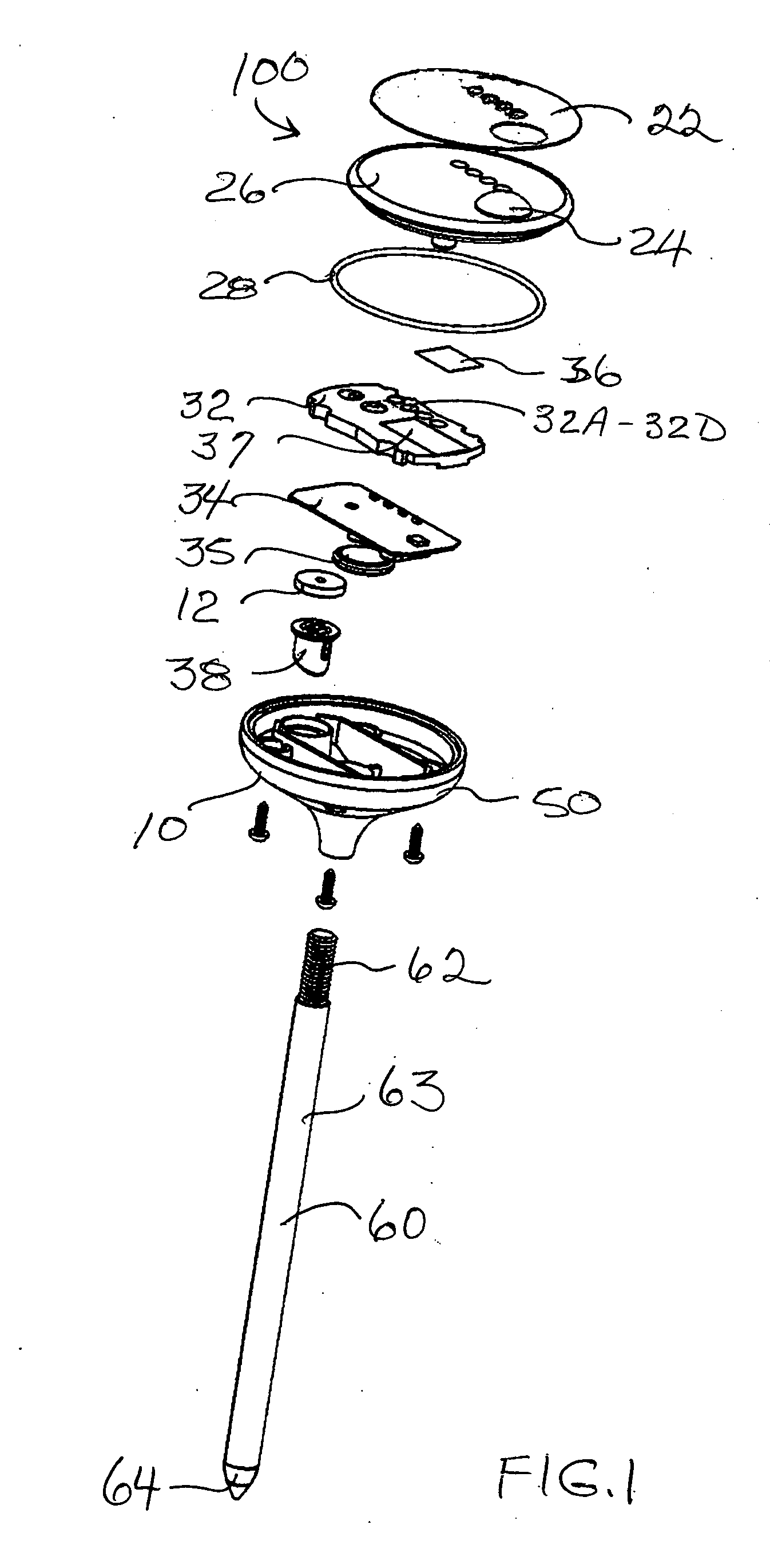
[0022]FIG. 1 shows the exploded assembly view of a sunlight measuring device 100 according to the invention, comprising a sunlight display panel 20, a sunlight measurement means 30, and a base 50.

[0023] The sunlight display panel 20 comprises a faceplate 22, a protective lens 26 that includes a sunlight collector lens 24 that allows sunlight to pass through to the sunlight measurement means 30, and four light condition indicators 25, which include a full sun indicator 25A, a partial sun indicator 25B, a partial shade indicator 25C, and a full shade indicator 25D. The sunlight display panel 20 is securely attached to the base 50, which together form a housing 10 for the sunlight measurement means 30, which includes a light filter 36 and a printed circuit board 34 mounted on a chassis 32 and a power source 35.

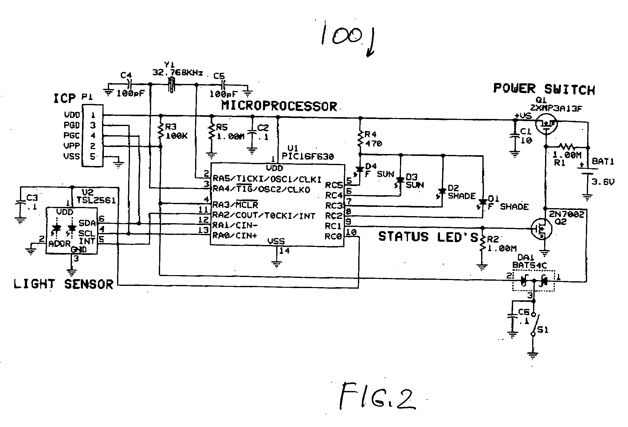
[0024]FIG. 2 is a schematic diagram of the electronic components of the sunlight measuring device 100. FIGS. 3A and 3B show the layout of the printed circuit board 34 and the v...


PUM

PropertyMeasurementUnit
timeaaaaaaaaaa
timeaaaaaaaaaa
timeaaaaaaaaaa

Abstract

A sunlight measuring device that quantifies the accumulation of light at a particular site. The sunlight measuring device is a battery-operated device mounted on a stake for easy insertion into the ground. The device is placed at the intended site for growing a plant. The light that falls on the sunlight measuring device over a period of time is accumulated and the light accumulation is represented by a visual signal that indicates one of four light conditions: full sun, partial sun, partial shade, full shade.

Description

BACKGROUND INFORMATION [0001] 1. Field of the Invention [0002] The invention relates to the field of devices that measure solar radiation. More specifically, this invention relates to a device that measures the amount of accumulated sunlight that is received at a specific location over a particular period of time. [0003] 2. Description of the Prior Art [0004] All plants require some level of sunlight in order to grow and thrive. Evolution has created differences in the cell structure of plants and, as a result, different plants require different light conditions to grow. Some plants require full sunlight conditions throughout the day while others thrive in total shade. [0005] Gardeners and landscapers are well aware of the need to match the light requirements of a plant with the light condition of specific planting site, but often lack the necessary tools to accurately measure accumulated sunlight conditions at the site over a period of time. The information typically provided on th...

Claims


Application Information

Patent Timeline
Patent Type & Authority Applications(United States)
IPC IPC(8): G01J1/42G01N21/25
CPCG01J1/0219G01J1/0271G01W1/12G01J2001/4266G01J1/42
Inventor BICKEL, WILLIAM C.RICHARDSON, JAMES E.
Owner BAR DEV
Learn More