Telescopic shaft for vehicle steering

a technology for steering shafts and vehicles, applied in the direction of movable seats, couplings, rod connections, etc., can solve the problems of large abrasion is notably quickened, and the backlash in the direction of rotation may become great in such a case, so as to reduce contact pressure, improve the durability of the shaft, and high rigidity

Active Publication Date: 2006-02-23
NSK LTD
View PDF53 Cites 31 Cited by
  • Summary
  • Abstract
  • Description
  • Claims
  • Application Information

AI Technical Summary

Benefits of technology

[0013] The present invention has been contrived taking such circumstances as described above into consideration, and an object thereof is to provide a telescopic shaft for vehicle steering which is capable of achieving a stable sliding load and, at the same time, preventing backlash in a direction of rotation, thereby transmitting torque in a state of high rigidity, with the improved durability and with the function of preventing hysteresis from becoming excessively great.
[0022] As described above, according to the telescopic shaft for vehicle steering of the present invention, since a columnar member serving as the sliding member is provided, in addition to a spherical member serving as the rolling element, when great torque is inputted, most of the load amount can be supported by the sliding member (columnar member). As a result, it is possible to improve the durability of the shaft by decreasing the contact pressure between the groove extended in the axial direction of the male shaft or the female shaft, the raceway element, and the rolling element (spherical member). At the same time, it is possible to transmit, when the torque load is great, the torque in a state of high rigidity.
[0023] Also, since the sliding member (columnar member) is in contact with the male shaft and the female shaft, it is possible to reduce the torsional torque toward the rolling element (spherical member) and to prevent a lateral slide of the raceway surface element. As a result, it is possible to suppress hysteresis from being excessively great.
[0024] As seen from the above description, according to the telescopic shaft for vehicle steering of the present invention described above, it is possible to realize a stable sliding load and, at the same time, to prevent backlash in the direction of rotation without fail, thereby transmitting the torque in a state of high rigidity.
[0025] Further, according to the telescopic shaft for vehicle steering of the present invention, it is possible to make the raceway surface element the columnar member which has the central axis thereof in a line with the axial grooves. In this case, since the raceway surface element is the columnar member having the central axis thereof in a line with the axial grooves, several sizes of columnar members can be employed as the raceway surface elements, and a desired preload can be generated by controlling an interference. As a result, it is possible to reduce a fluctuation in the preload and the torsional rigidity which is caused by manufacturing errors (dimensional errors) of the male shaft, the female shaft and the elastic member. It is also possible to achieve lower manufacturing cost by simplifying the form of the raceway surface element.

Problems solved by technology

However, there is a case that abrasion of the nylon film advances with use and the backlash in the direction of rotation becomes great.
Also, under the high-temperature condition inside the engine room, a nylon film is changed in volume, so that a sliding resistance becomes conspicuously great or the abrasion is notably quickened sometimes, and resultantly, the backlash in the direction or rotation may become great in such a case.
As a result, an increased fluctuation of the sliding load or deteriorated torsional rigidity is brought about.
With an increase of the torsional torque, a lateral slide of the raceway element with respect to the male shaft may be increased so that hysteresis becomes excessively great.
Further, an amount of preloading and the torsional rigidity may be fluctuated due to a manufacturing error (dimensional error) of each of the male shaft, the female shaft, the elastic member, and the raceway surface element.

Method used


Image

  • Telescopic shaft for vehicle steering
  • Telescopic shaft for vehicle steering
  • Telescopic shaft for vehicle steering

Examples


first embodiment

(First Embodiment)

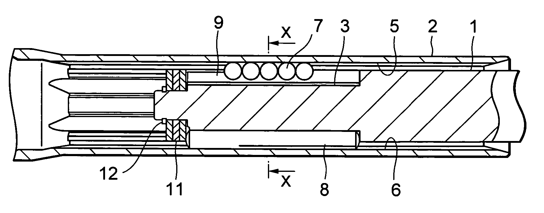
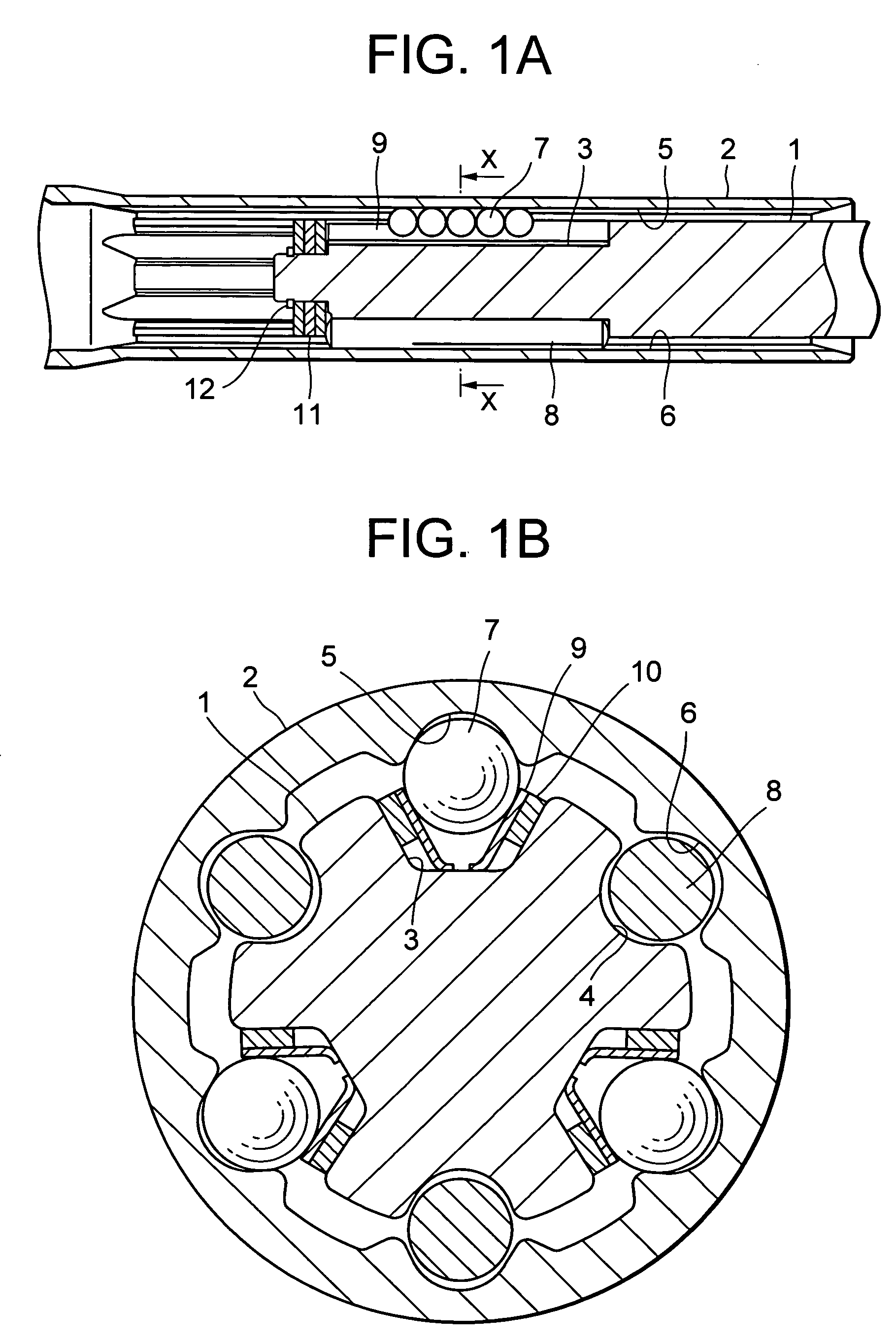
[0036]FIG. 1A is a longitudinal cross sectional view of a telescopic shaft for vehicle steering according to a first embodiment of the present invention, and FIG. 1B is a transverse cross sectional view of the telescopic shaft, taken along the line X-X in FIG. 1A.

[0037] As shown in FIG. 1A, the telescopic shaft for vehicle steering (hereinafter called the “telescopic shaft”) comprises a male shaft 1 and a female shaft 2 which are fitted to each other to be unrotatable and slidable.

[0038] As shown in FIG. 1B, three grooves 3 are provided on the outer peripheral surface of the male shaft 1 at regular intervals of 120° in the circumferential direction to be extended in the axial direction. To be corresponding thereto, on the inner peripheral surface of the female shaft 2, there are provided three grooves 5 which are extended in the axial direction at regular intervals (phase) of 120° in the circumferential direction.

[0039] Between the axial grooves 3 of the male sh...

second embodiment

(Second Embodiment)

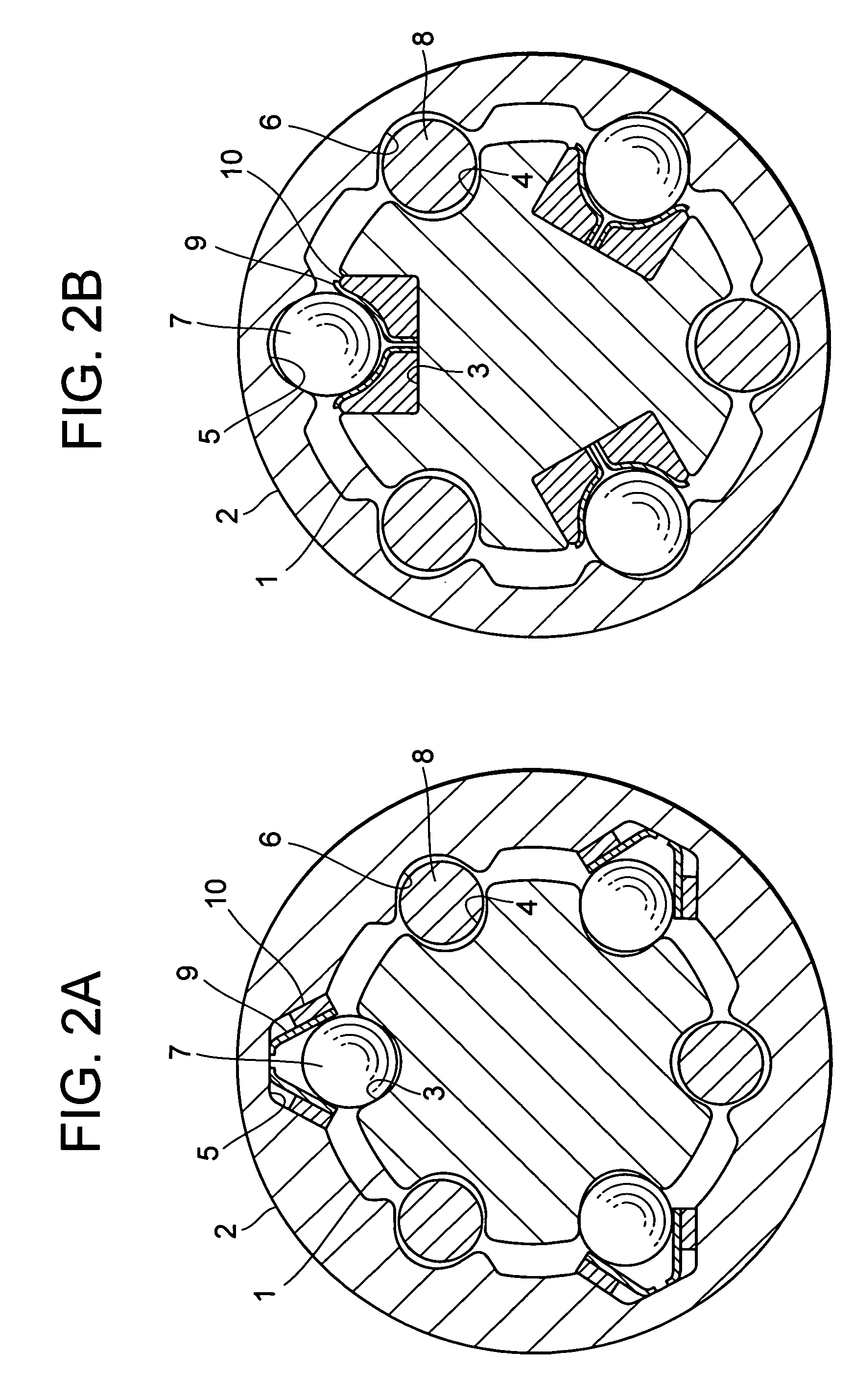
[0081]FIG. 3A is a transverse cross sectional view of a telescopic shaft for vehicle steering according to a second embodiment of the present invention (corresponding to the transverse cross sectional view, taken along the line X-X in FIG. 1A).

[0082] In the second embodiment, a pair of raceway surface elements 9 made of needle rollers which are brought into contact with spherical members 7 and a elastic member 10 which is formed of rubber, or the like, for preloading the spherical members 7 against the male shaft 1 and the female shaft 2 through these raceway surface elements 9 is interposed between axial grooves 5 of the female shaft 1 and the spherical members 7. In this case also, the mode of operation is the same as in the first embodiment described above.

[0083] Note that the axial groove 5 is constituted by a substantially flat bottom portion and substantially flat side surfaces each having an almost right angle with respect to the bottom portion. The botto...

third embodiment

(Third Embodiment)

[0086]FIG. 3B is a transverse cross sectional view of a telescopic shaft for vehicle steering according to the third embodiment of the present invention (corresponding to the transverse cross sectional view, taken along the line X-X in FIG. 1A).

[0087] In the third embodiment, the raceway surface element 9 is formed of metal to take the form of a guide rail. The elastic member 10 is formed of a leaf spring which is integrally formed to be line symmetrical with both ends thereof folded back. Also in this case, the mode of operation is the same as in the first embodiment described above.

[0088] Note that the axial groove 3 is constituted by a substantially flat bottom portion and substantially flat side surfaces each having a predetermined angle with respect to the bottom portion. The bottom portion and the side surface may have a predetermined angle therebetween or may be at right angles.

[0089] The paired raceway surface elements 9 are separated right and left, and...


PUM


Abstract

According to the present invention, a rolling element 7 for rotating upon relative movement of both shafts 1 and 2 in the axial direction is disposed between three pairs of axial grooves 3 and 5 which are formed on the outer peripheral surface of the male shaft 1 and on the inner peripheral surface of the female shaft 2, respectively, a raceway surface element 9 which is in contact with the rolling element 7 and an elastic member 10 for pressurizing the rolling element 7 against the male shaft 1 and the female shaft 2 through the raceway surface element 9 are interposed between the axial groove 3 on the male shaft side 1 and the rolling element 7, and a sliding member 8 for slidably moving upon relative movement of the both shafts 1 and 2 in the axial direction is disposed between another three pairs of axial grooves 4 and 6 which are formed on the outer peripheral surface of the male shaft 1 and on the inner peripheral surface of the female shaft 2, respectively.

Description

TECHNICAL FIELD [0001] The present invention relates to a telescopic shaft for vehicle steering which is installed in a steering shaft of a vehicle and in which a male shaft and a female shaft are fitted to each other to be mutually unrotatable and slidable. BACKGROUND ARTS [0002] A telescopic shaft of a steering mechanism of a vehicle is required to have a property of absorbing an axial displacement which is generated when the vehicle is running and of preventing such displacement or vibration from being propagated onto a steering wheel. Further, the telescopic shaft is also required to have a function of moving the position of the steering wheel in the axial direction and of adjusting this position in order to obtain an optimal position for the driver to drive the vehicle. [0003] In any of these cases, the telescopic shaft is required to reduce rattling sound, to decrease backlash feeling on the steering wheel, and to reduce a sliding resistance during a sliding operation in the a...

Claims


Application Information

Patent Timeline
Patent Type & Authority Applications(United States)
IPC IPC(8): F16B7/10B62D1/185F16D3/06
CPCB62D1/185F16D3/065F16C3/035Y10T403/32467F16C29/123F16C2326/24F16C29/04F16C29/007
Inventor SHODA, AKIHIROYAMADA, YASUHISA
Owner NSK LTD
Why Eureka
Try Eureka