Plastic screw cap

a screw cap and plastic technology, applied in the direction of threaded fasteners, mechanical equipment, transportation and packaging, etc., can solve the problems of increasing manufacturing costs, time-consuming, and complicated screw caps on the inlet connection of tapping valves

Inactive Publication Date: 2006-02-23
PROTECHNA SA
View PDF5 Cites 23 Cited by
  • Summary
  • Abstract
  • Description
  • Claims
  • Application Information

AI Technical Summary

Benefits of technology

[0005] The object of the invention is the further development of this general type of screw cap with respect to simplified assembly.

Problems solved by technology

This type of captive mounting of a screw cap on the inlet connection of a tapping valve is complicated and time-consuming and increases manufacturing costs.

Method used


Image

  • Plastic screw cap
  • Plastic screw cap
  • Plastic screw cap

Examples


Embodiment Construction

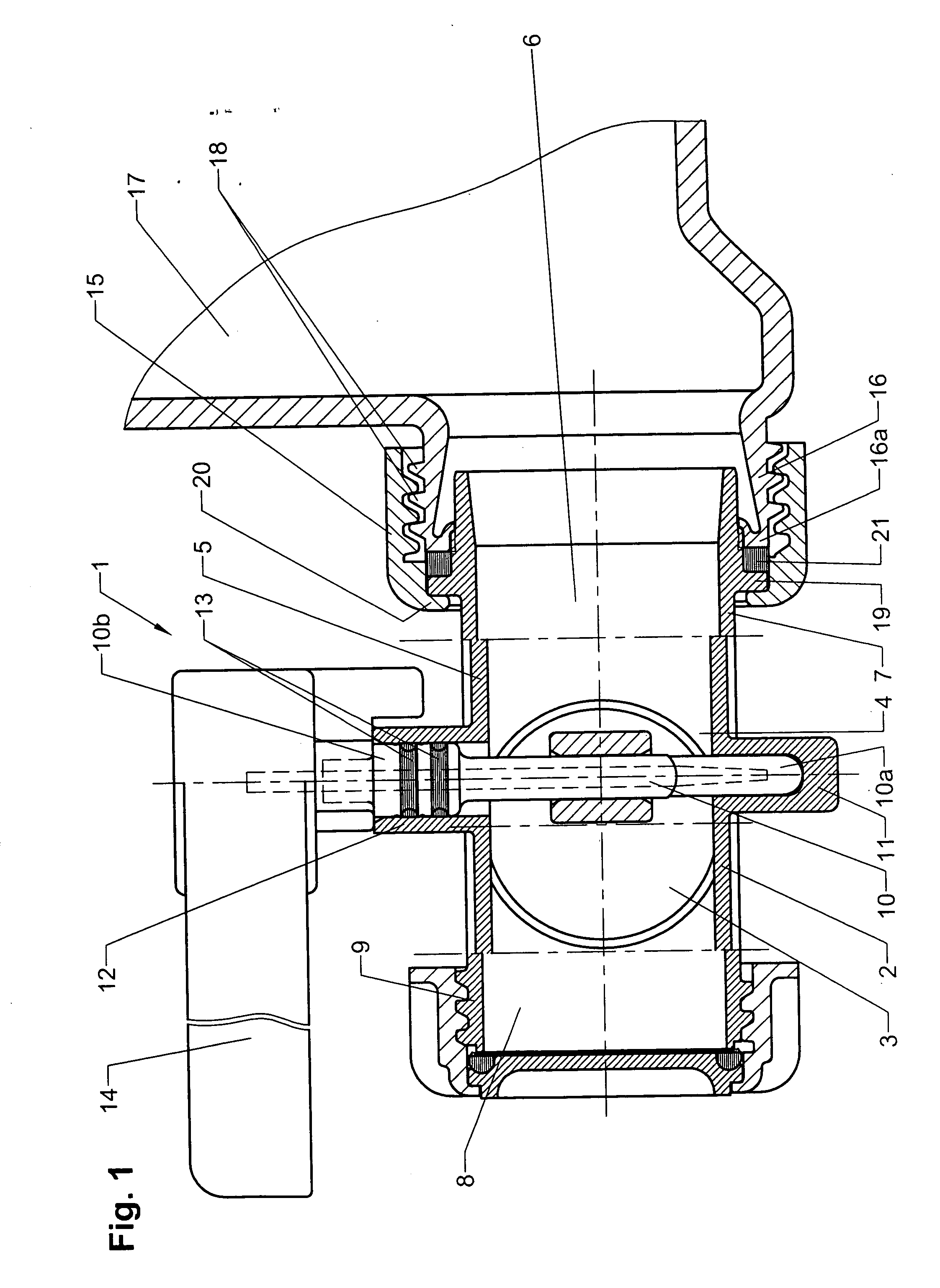
[0019] The HDPE (high-density polyethylene) valve body 2 of the flap valve 1 shown in FIG. 1 holds a flap disk 3 for opening and closing the central flow passage 4 of the body chamber 5, which communicates with the inlet channel 6 of the inlet connection 7 and with the outlet channel 8 of the outlet connection 9 of the valve body 2. The flap disk 3 is eccentrically mounted on a rotating shaft 10, whose two ends 10a, 10b are rotatably supported in support studs 11, 12 of the valve body 2, and the upper end 10b of the rotating shaft 3 extends out of the valve body 2 beyond the support stud 12. The rotating shaft 10 is sealed towards the outside by gaskets 13 in the support stud 12. A handle 14 for opening and closing the flap valve 1 is mounted on the end 10b of the rotating shaft 10 of the flap disk 3 that extends from the valve body 2.

[0020] The flap valve 1 is mounted on the outlet connection 16 of a liquid tank 17, e.g., a plastic inner tank of a pallet tank, by means of a plasti...


PUM


Abstract

A plastic screw cap includes two cap halves, which are produced as plastic injection-molded parts and have an internally threaded segment and an inwardly directed ring shoulder segment. The two halves of the screw cap can be pushed together, for example, on the inlet connection of the valve body of a flap valve by tongue-and-groove joints. One cap half has two hook-like ends, each of which is provided with an inwardly sloped clamping sidepiece and a groove for receiving the tongues formed on the two ends of the other half of the screw cap.

Description

BACKGROUND OF THE INVENTION [0001] 1. Field of the Invention [0002] The present invention relates to a plastic screw cap composed of two cap halves on a first component wherein the screw cap is captively held on this first component, and wherein the cap halves each have an internally threaded segment and an inwardly directed ring shoulder segment for making contact with a corresponding collar of the first component, which is to be screwed together with a second component, especially for screwing the valve body of a tapping valve on the externally threaded outlet connection of a plastic or metal shipping and storage tank for liquids and loose bulk material. [0003] 2. Description of the Related Art [0004] DE 103 01 517 B3 describes a shipping and storage tank for liquids with an inner plastic tank that stands on a pallet-like frame and an outer cage. The tapping valve of the inner tank is screwed onto the outlet connection of the inner tank by means of a plastic screw cap of a generic...

Claims


Application Information

Patent Timeline
Patent Type & Authority Applications(United States)
IPC IPC(8): F16B37/08B65D
CPCF16B37/0885F16L19/0231F16B37/0892B67D3/04B67D3/047
Inventor SCHUTZ, UDO
Owner PROTECHNA SA
Why Eureka
Try Eureka