

Liquid circulation type fuel cell
a fuel cell and liquid circulation technology, applied in the direction of fuel cells, fuel cells, solid electrolyte fuel cells, etc., can solve the problems of reducing and reducing the power consumption of the fuel. dilution and other problems, to achieve the effect of improving the efficiency of the fuel cell and reducing the power consumption of the fuel
- Summary
- Abstract
- Description
- Claims
- Application Information
AI Technical Summary
Benefits of technology
Problems solved by technology
Method used
Image

Examples
first embodiment
of the Liquid Circulation Fuel Cell
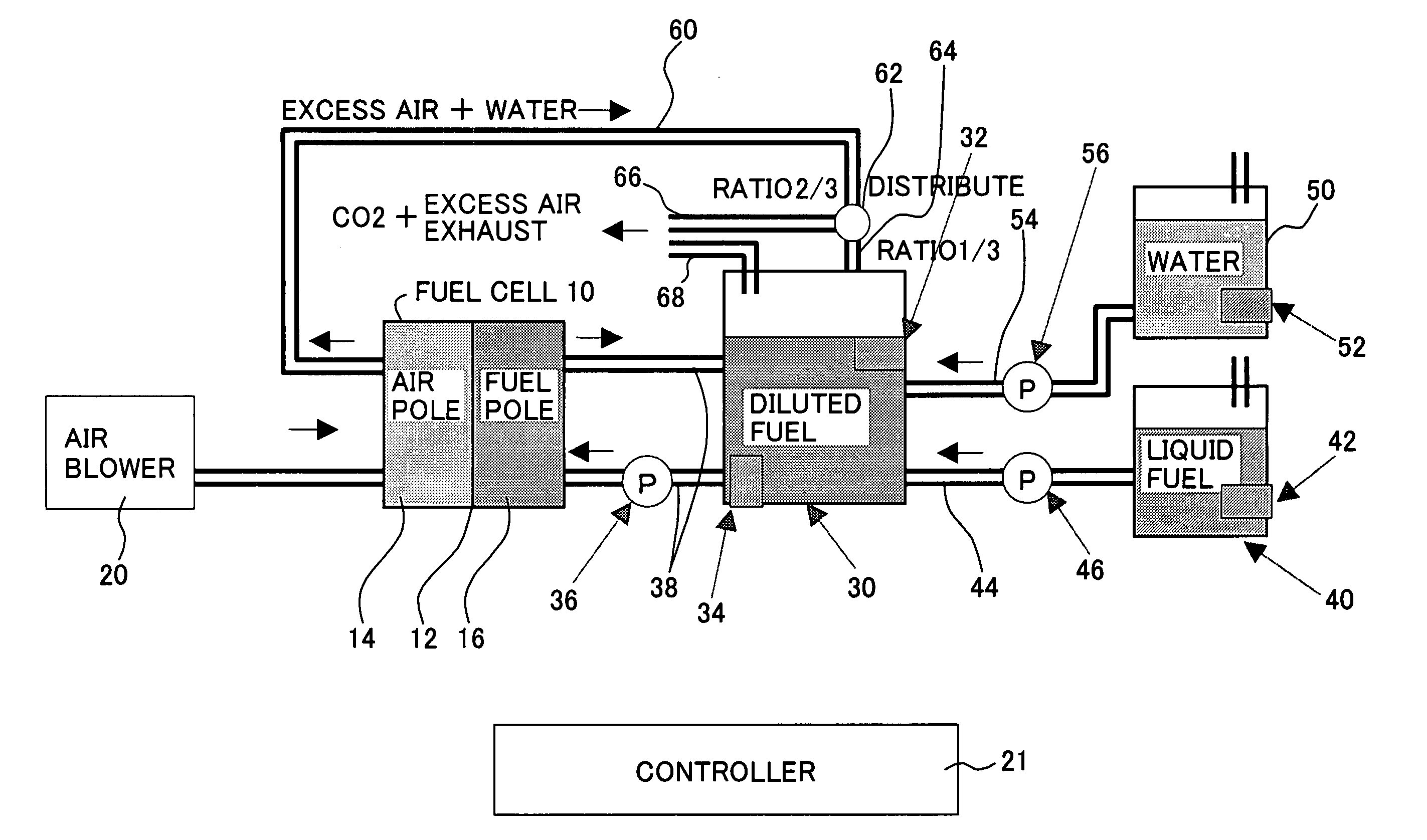
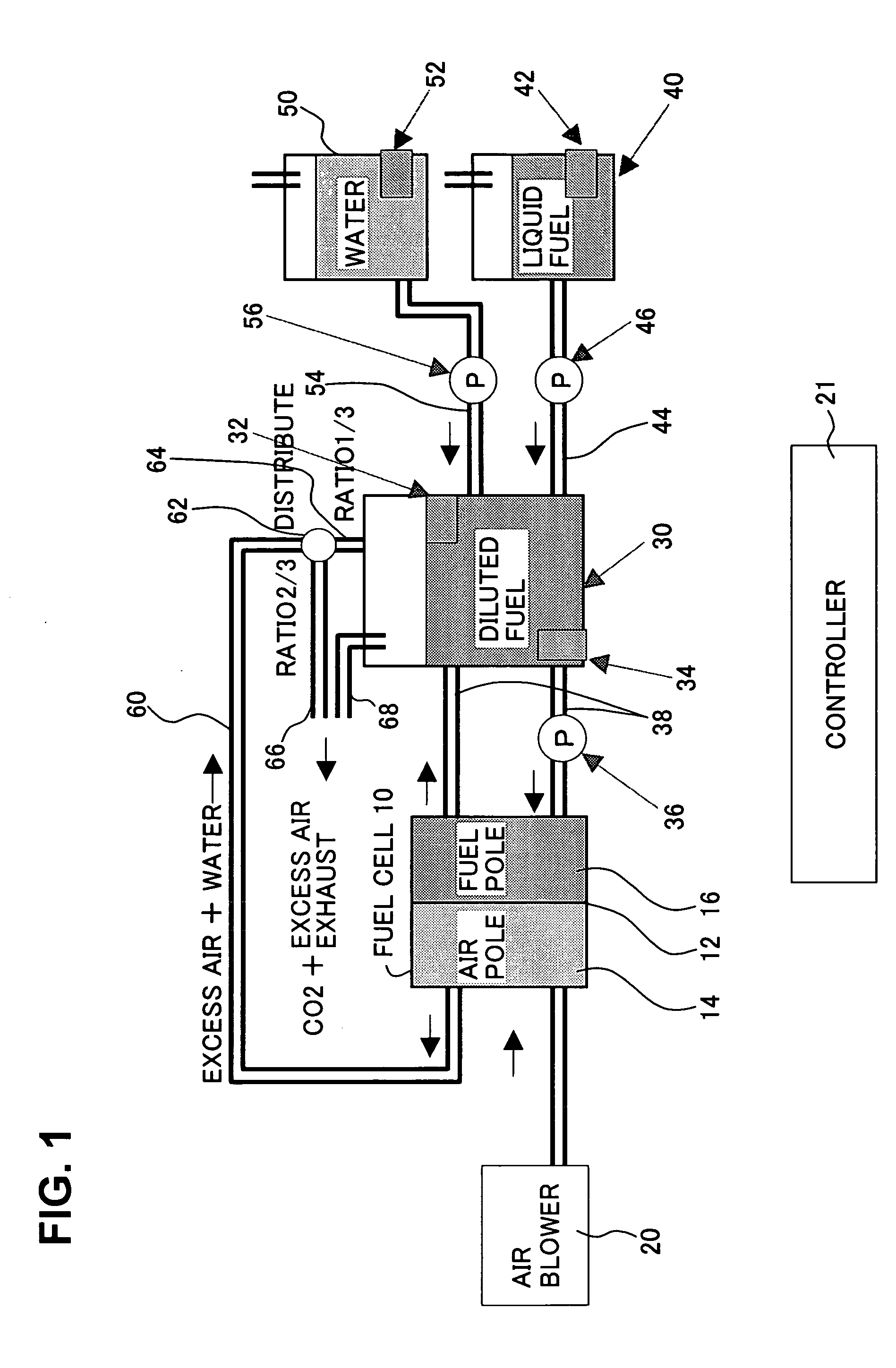
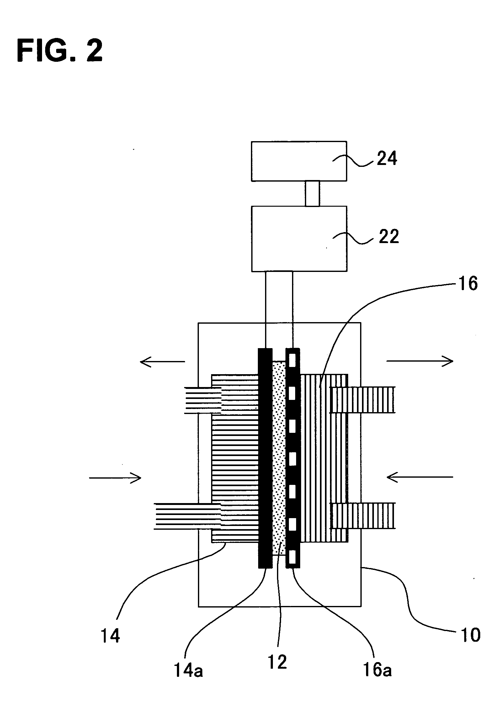
[0047]FIG. 1 shows a configuration diagram of a liquid circulation type fuel cell according to a first embodiment of the present invention. FIG. 2 shows a configuration diagram of the liquid fuel cell shown in FIG. 1. Further, FIG. 3 shows a configuration diagram of an electronic apparatus, in which the liquid fuel cell shown in FIG. 1 is applied, as one example. As shown in FIG. 1, a fuel cell 10 includes an electrolyte membrane 12, and also, an air pole 14 and a fuel pole 16 sandwiching the electrolyte membrane 12. As shown in FIG. 2, the electrolyte membrane 12 is constituted of a substance capable of permeating protons or electrons, such as a polymer electrolyte membrane, including a proton-conductive solid polymer membrane like Nafion (brand mark of DuPont Ltd.) of perfluoro sulphonic acid. On both sides of the electrolyte membrane 12, fuel electrode 16a and an oxidant electrode 14a are disposed, thereby constituting an electrolyte plate.
[004...
second embodiment
of the Liquid Circulation Fuel Cell
[0070]FIG. 5 shows a configuration diagram of a liquid circulation type fuel cell according to a second embodiment of the present invention. FIG. 6 shows an operation process flowchart of the fuel cell shown in FIG. 5. In this FIG. 5, like parts shown in FIGS. 1 and 3 are referred to by like numerals. Namely, as shown in FIG. 5, the fuel cell 10 includes an electrolyte membrane 12, and also, an air pole 14 and a fuel pole 16 sandwiching the electrolyte membrane 12. As shown in FIG. 2, the fuel cell 10 includes the electrolyte membrane 12. This electrolyte membrane 12 is constituted of a substance capable of permeating protons or electrons, such as a polymer electrolyte membrane, including a proton-conductive solid polymer membrane like Nafion (brand mark of DuPont) of perfluorosulphonic acid. On both sides of the electrolyte membrane 12, fuel electrode 16a and an oxidant electrode 14a are disposed, which constitutes an electrolyte plate.
[0071] Air...
third embodiment
of the Liquid Circulation Fuel Cell
[0087]FIG. 7 shows a configuration diagram of a liquid circulation fuel type cell according to a third embodiment of the present invention. The configuration shown in FIG. 7 is obtained by combining the configuration of the first embodiment shown in FIG. 1 with the configuration of the second embodiment shown in FIG. 5. In FIG. 7, like parts shown in FIGS. 1 through 3 and FIG. 5 are referred to by like numerals.
[0088] Namely, as shown in FIG. 7, the fuel cell 10 includes an electrolyte membrane 12, and also, an air pole 14 and a fuel pole 16 sandwiching the electrolyte membrane 12. As shown in FIG. 2, the fuel cell 10 includes the electrolyte membrane 12. This electrolyte membrane 12 is constituted of a substance capable of permeating protons or electrons, such as a polymer electrolyte membrane, including a proton-conductive solid polymer membrane like Nafion (brand mark of DuPont) of perfluorosulphonic acid. On both sides of the electrolyte membr...
PUM
 Abstract
Description
Claims
Application Information