Method and apparatus for transmission power control

a technology of transmission power and power control, applied in the direction of power management, sustainable buildings, wireless communication, etc., can solve the problems of complex management and control of different mobile stations, unsuitable for efficient resource utilisation, and limited frequency band allocated for cellular communication systems, etc., to achieve the effect of reducing, alleviating or eliminating one or mor

Active Publication Date: 2006-02-23
GOOGLE TECH HLDG LLC
View PDF6 Cites 91 Cited by
  • Summary
  • Abstract
  • Description
  • Claims
  • Application Information

AI Technical Summary

Benefits of technology

[0012] Accordingly, the Invention seeks to mitigate, alleviate or eliminate one or more of the above mentioned disadvantages singly or in any combination.

Problems solved by technology

The frequency band allocated for a cellular communication system is typically severely limited, and therefore the resource must be effectively divided between mobile stations.
However, the allocation of resource to different services and different mobile stations tend to require complex management and control involving significant signalling.
This is particularly unsuitable for efficient resource utilisation in the presence of significant fluctuations in the radio environment.
However, handover is a slow process that requires significant signalling between base stations and mobile stations.
Therefore, repeated handovers must be avoided and consequently handovers are best suited to permanent changes in the radio environment and less suited for dealing with short term variations.
However, these algorithms require complex signalling and are therefore unsuitable for short term fluctuations in the parameters of the radio environment.

Method used


Image

  • Method and apparatus for transmission power control
  • Method and apparatus for transmission power control
  • Method and apparatus for transmission power control

Examples


Embodiment Construction

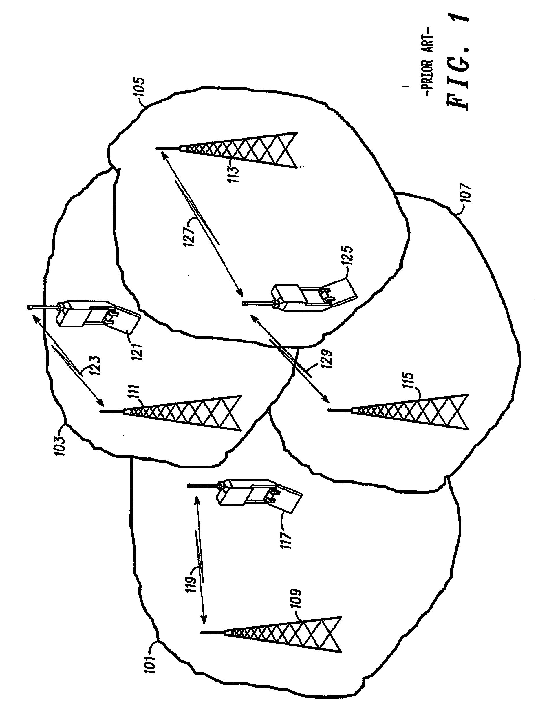
[0039] The following description focuses on an embodiment of the invention applicable to a Universal Mobile Telecommunication System (UMTS). Specifically, the description will concentrate on an embodiment wherein power control is performed in accordance with 3rd Generation Partnership Project Technical Specification TS 25.214. However, it will be appreciated that the invention is not limited to this application but may be applied to many other cellular communication systems including for example 2nd generation communication systems such as GSM and GPRS based communication systems.

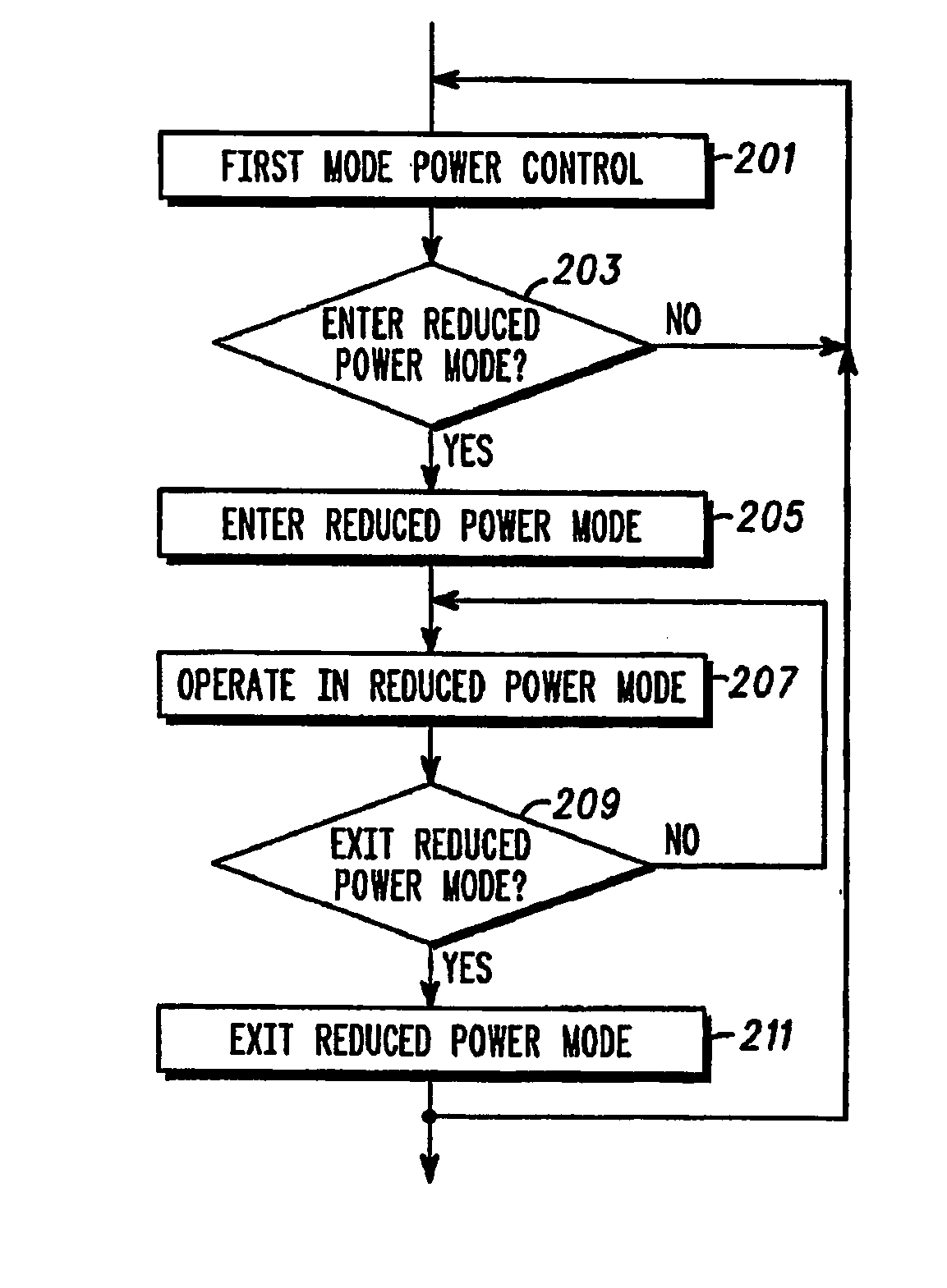
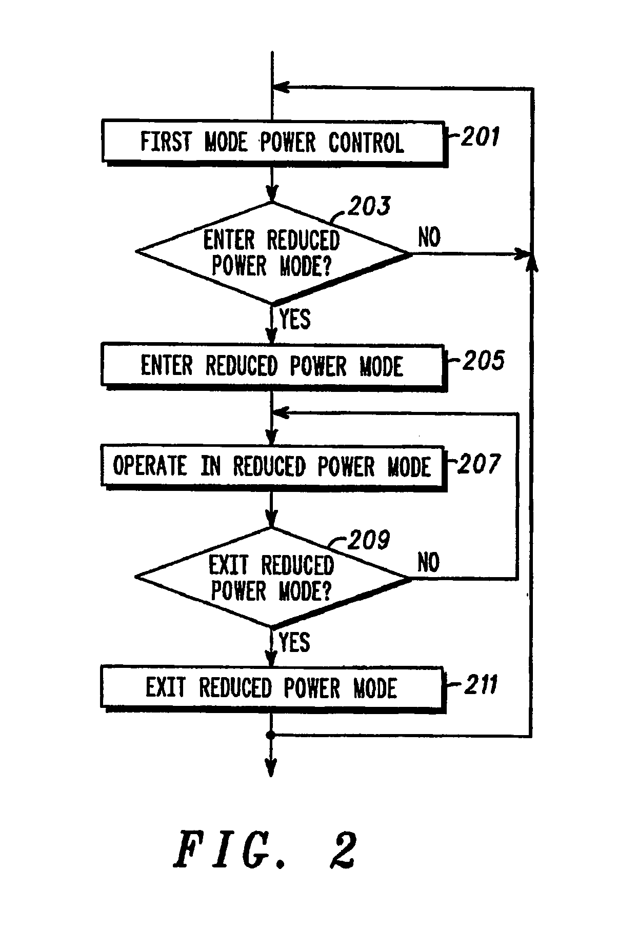
[0040] The following description will furthermore focus on a description wherein an uplink power control is used to reduce the transmit power of a communication unit. However, it will be apparent that the invention is not limited to this application and is for example equally applicable to down link power control. A method of power control in accordance with an embodiment of the invention. will in the foll...


PUM


Abstract

The invention relates to a system for power control in a cellular communication system. The power control may be operated (201) in a first mode of operation wherein power control data are determined in response to a quality parameter, such as a desired signal to noise ratio. The method further comprises entering (205) a reduced power mode of operation by communicating power down power control data between a base station and a communication unit. The base station and/or communication unit then proceeds to operate (207) in the reduced power mode by communicating power control data corresponding to a reduced transmit power level. The reduced transmit power level may specifically be zero. After a given duration, the base station and/or communication unit proceeds to exit (211) the reduced power mode by communicating power up power control data between the base station and the communication unit.

Description

FIELD OF THE INVENTION [0001] The invention relates to a method and apparatus for power control for a transmitter in a cellular communication system and in particular to a system for entering a reduced power control mode. BACKGROUND OF THE INVENTION [0002]FIG. 1 illustrates the principle of a conventional cellular communication system 100 in accordance with prior art. A geographical region is divided into a number of cells 101, 103, 105, 107 each of which is served by base station 109, 111, 113, 115. The base stations are interconnected by a fixed network which can communicate data between the base stations 109, 111, 113, 115. A mobile station is served via a radio communication link by the base station of the cell within which the mobile station is situated. In the example of FIG. 1, mobile station 117 is served by base station 109 over radio link 119, mobile station 121 is served by base station 111 over radio link 123 and so on. [0003] As a mobile station moves, it may move from ...

Claims


Application Information

Patent Timeline
Patent Type & Authority Applications(United States)
IPC IPC(8): H04B7/00H04Q7/20H04B1/707H04B7/005H04J13/00H04W52/24H04W52/26H04W52/34H04W52/36H04W52/44
CPCH04W52/24H04W52/26Y02B60/50H04W52/367H04W52/44H04W52/34
Inventor LIN, JIE
Owner GOOGLE TECH HLDG LLC
Why Eureka
Try Eureka