Propeller shaft and rotational power transmission mechanism equipped with this

a technology of power transmission mechanism and gear shaft, which is applied in the direction of shafts, shafts, mechanical equipment, etc., can solve the problems of low impact energy absorption performance, the gear shaft may interfere with the engine recession and the transmission, etc., and achieve the effect of simple construction

Inactive Publication Date: 2006-02-23
HONDA MOTOR CO LTD
View PDF6 Cites 13 Cited by
  • Summary
  • Abstract
  • Description
  • Claims
  • Application Information

AI Technical Summary

Benefits of technology

[0007] To solve the above mentioned problem, it is an object of the present invention to provide a propeller shaft whose specific part collapses by an axial compressive force generated from a collision and which propeller shaft has a relatively simple construction. It is also an object of the present invention to provide a rotational power transmission mechanism equipped with such a propeller shaft.

Problems solved by technology

In this case, if the vehicle comprises a rotational power transmission mechanism, which transmits the rotational driving force from the transmission through the propeller shaft to the rear axle device as mentioned above, then the propeller shaft may interfere with the recession of the engine and the transmission.
Especially, if the propeller shaft is an FRP propeller shaft, which has a high rigidity against a compressive force in its axial direction and therefore shows a property of low impact energy absorption, then the FRP propeller shaft can obstruct an appropriate recessive movement of the engine, etc., which will result in a low performance of impact energy absorption.

Method used


Image

  • Propeller shaft and rotational power transmission mechanism equipped with this
  • Propeller shaft and rotational power transmission mechanism equipped with this
  • Propeller shaft and rotational power transmission mechanism equipped with this

Examples


Embodiment Construction

[0022] Now, the power transmission of an automobile with a propeller shaft according to the present invention is described in reference to the drawings.

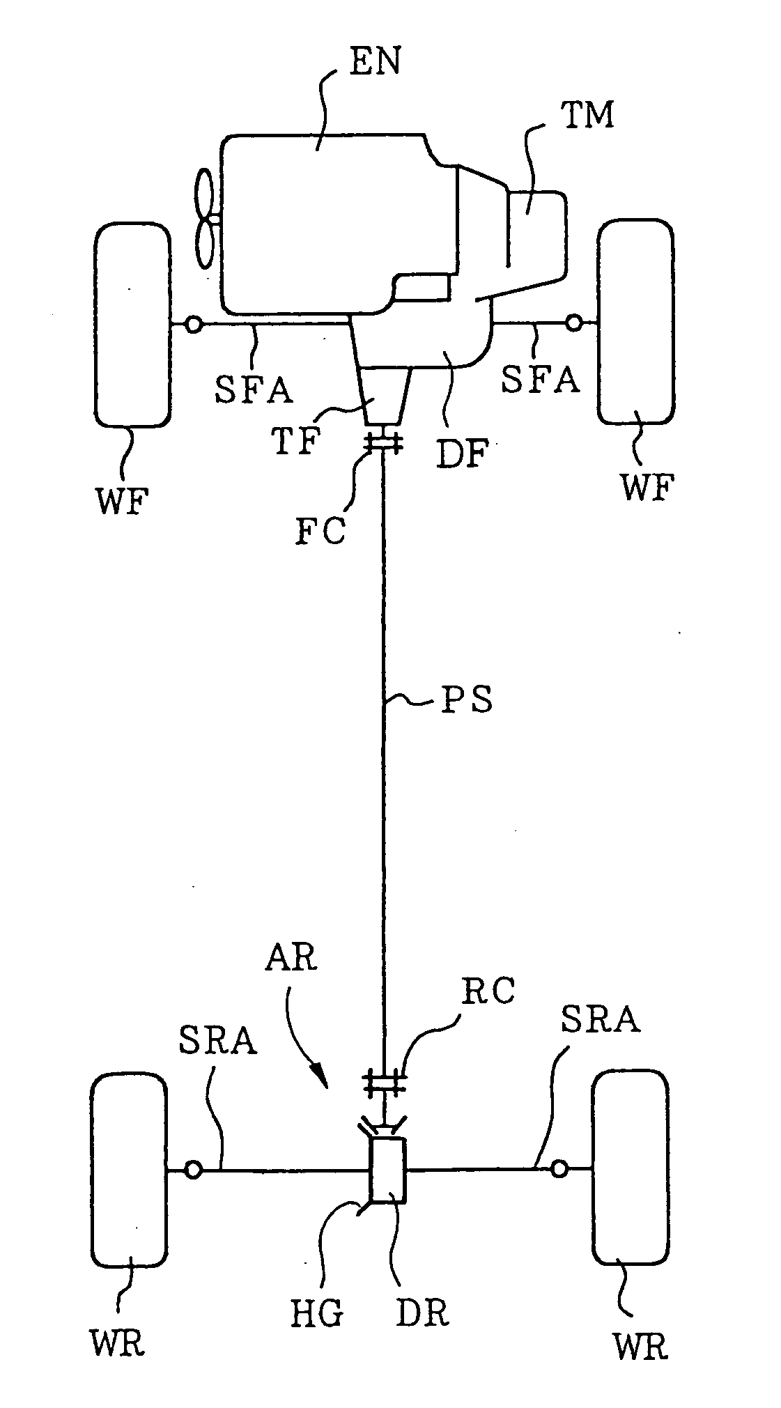
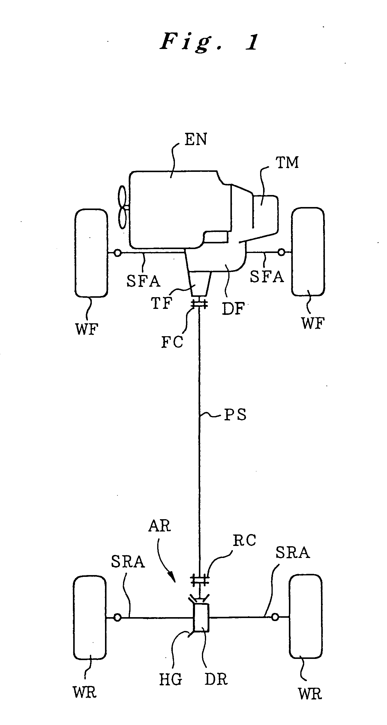
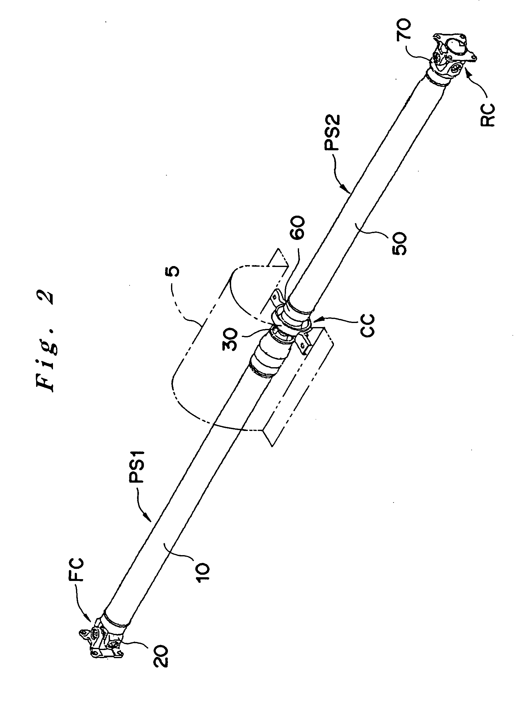
[0023] The automobile shown in FIG. 1 is a four-wheel drive vehicle and comprises an engine EN, which is oriented laterally at the front part of the vehicle, and a transmission TM, which is coupled to the output side of the engine EN as a unit. The transmission TM includes a front differential mechanism DF and a transfer mechanism TF. The power of the engine EN with a speed ratio change by the transmission TM is transmitted through the front differential mechanism DF and divided to right and left front axle shafts SFA for driving the right and left front wheels WF. The power of the engine EN is also divided through the transfer mechanism TF, and the power is transmitted from a front coupling FC to a front propeller shaft PS1. As also shown in FIG. 2, the front propeller shaft PS1 is coupled through a center coupling CC with a rear p...


PUM


Abstract

A propeller shaft PS1 comprises a front pipe member 10 and first and second yoke members 20 and 30, which are attached to both the ends of the front pipe member 10. The first yoke member 20 is attached by press-fitting a first yoke fitting portion 23 into the inner circumferential part at the left end of the front pipe member 10 until the front end of the front pipe member comes near a stopper portion 24. The second yoke member 30, which has no stopper portion, is attached by press-fitting a second yoke fitting portion 33 into the inner circumferential part at the right end of the front pipe member 10. When a compressive force greater than a predetermined force acts axially, while the first yoke fitting portion 23 is prevented from being further inserted by the stopper portion 24, the second yoke fitting portion 33 is press-fit further into the inner circumferential part of the front pipe member, which is thereby expanded and destroyed.

Description

FIELD OF THE INVENTION [0001] The present invention relates to a propeller shaft which comprises a first yoke member and a second yoke member each attached at a respective end of a hollow pipe member and which is used for transmission of a driving force from the engine to drive wheels, for example, in an automobile. The present invention also relates to a rotational power transmission mechanism equipped with this propeller shaft. BACKGROUND OF THE INVENTION [0002] Automobiles of FR drive model or four-wheel drive model generally comprise, as a power transmission transmitting the rotational driving force of the engine to drive wheels, a rotational power transmission mechanism that transmits the rotational driving force from the transmission (rotational drive member), which outputs the power of the engine with speed ratio changes, through a propeller shaft (rotational power transmission member) to an axle device (rotational driven member). For example, the engine is placed in the fron...

Claims


Application Information

Patent Timeline
Patent Type & Authority Applications(United States)
IPC IPC(8): F16C3/00
CPCF16C3/026F16C2326/06
Inventor KAI, SHUNNOSUKEWADA, SHINJI
Owner HONDA MOTOR CO LTD
Why Eureka
Try Eureka