
Planetary reduction mechanism, pin structure, and method for manufacturing pin

a technology of planetary reduction and pin structure, which is applied in mechanical equipment, gearing, hoisting equipment, etc., can solve the problems of insufficient supply of lubricant such as grease to the sliding surface, inability to meet the function of lubricant, and the problem of increasing the difficulty of lubricant supply, so as to improve the basic quality or performance, the effect of simple process

Inactive Publication Date: 2006-02-23
SUMITOMO HEAVY IND LTD
View PDF7 Cites 20 Cited by
  • Summary
  • Abstract
  • Description
  • Claims
  • Application Information

AI Technical Summary

Benefits of technology

[0013] In view of the above problems in the conventional techniques, various exemplary embodiments of the present invention provide a structure of a pin extending through a planetary rotary member of the aforementioned type of planetary reduction mechanism and a method for manufacturing that pin, which can improve the basic quality or performance.
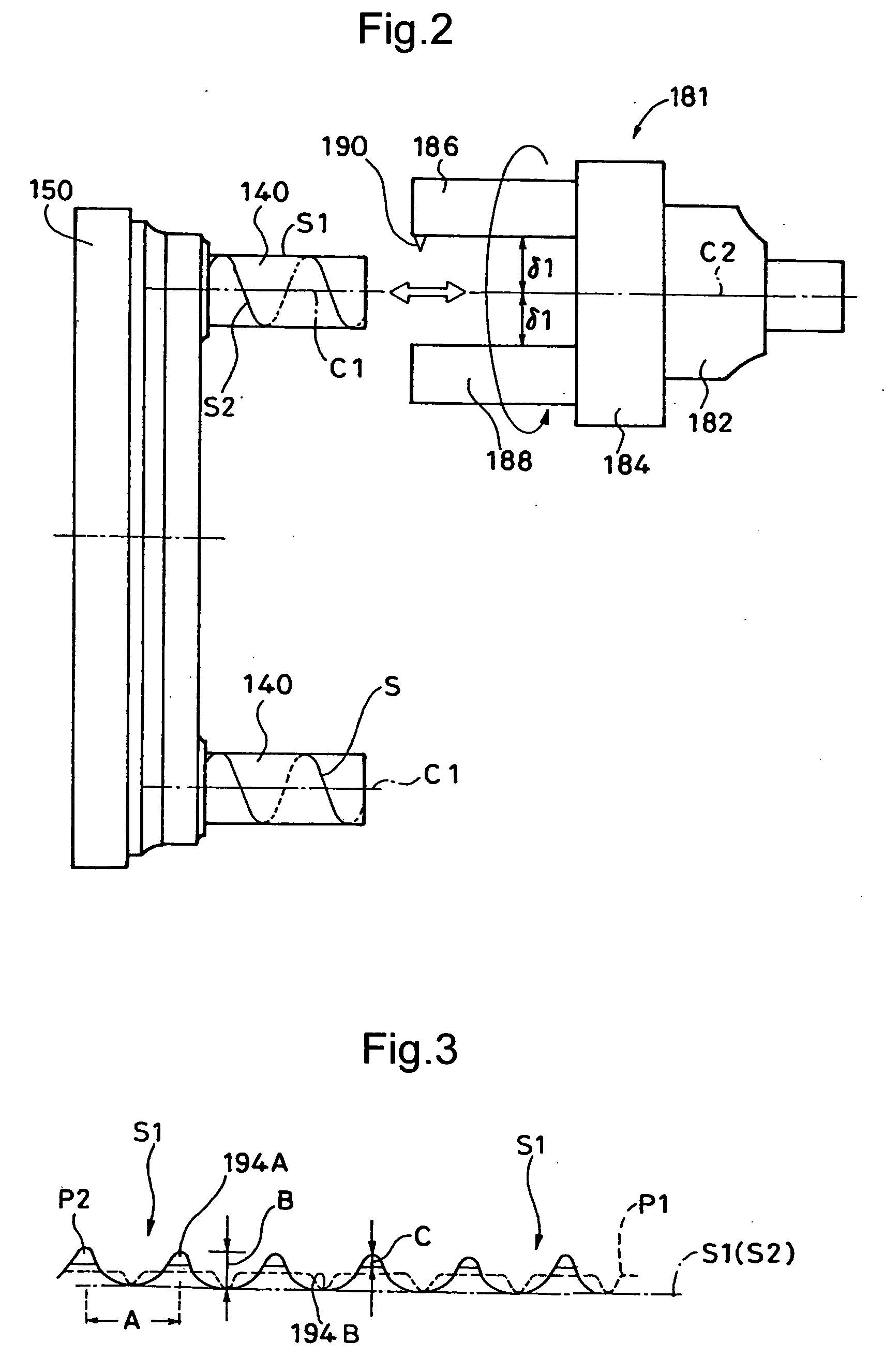
[0015] According to the present invention, the “continuous groove” is formed on the outer circumference of the pin extending through the planetary rotary member. Thus, it is possible to efficiently supply a lubricant such as grease or lubricating oil that exist around the pin of the planetary rotary member to an engaging surface of the pin and the planetary rotary member. This enables smooth sliding of the pin and the planetary rotary member with respect to each other. Since the continuous groove is continuously formed on the outer circumference of the pin literally, the lubricant entering the groove can be efficiently moved in an axial direction even if the lubricant enters the groove from any portion.
[0016] Consequently, favorable sliding property can be obtained only by performing a simple process for the outer circumference of the pin, and the inner pin that can slide more smoothly and has a longer life can be obtained.
[0022] In any of the above embodiments, an effective lubricating effect can be achieved for at least one of a sliding surface between the pin and the planetary rotary member, a sliding surface between the pin and the sliding facilitation member, and a sliding surface between the sliding facilitation member and the planetary rotary member.
[0023] As described above, the present invention can improve the basic quality or performance related to the inner pin only by performing a simple process.

Problems solved by technology

This type of planetary reduction mechanism has a problem that the lubricant such as grease is not sufficiently supplied to a sliding surface of the inner pin although the lubricant is put in the casing in order to facilitate the slidability of the respective parts.
That is, the lubricant does not fulfill its function.
This problem tends to become more apparent in an arrangement in which the sliding facilitation member such as the inner roller is arranged around the inner pin as in the above conventional example.
However, when a gap between the inner pin and the inner roller is made larger in order to make entering of grease to the sliding surface easier, for example, this causes eccentric movement of the inner roller with respect to the inner pin, thus increasing a noise and transmission loss.

Method used


Image

  • Planetary reduction mechanism, pin structure, and method for manufacturing pin
  • Planetary reduction mechanism, pin structure, and method for manufacturing pin
  • Planetary reduction mechanism, pin structure, and method for manufacturing pin

Examples


Embodiment Construction

[0029] Preferred exemplary embodiments of the invention will be hereinafter described with reference to the drawings.

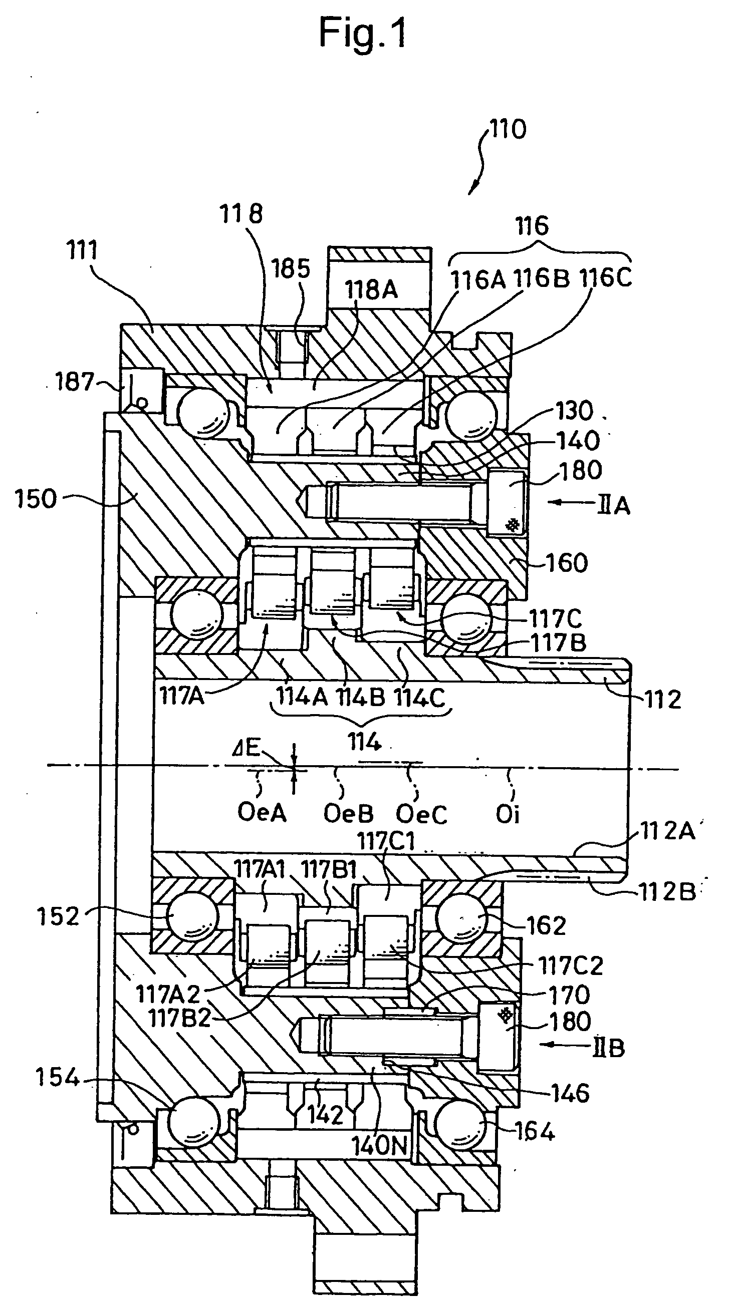
[0030]FIG. 1 is a vertical cross-sectional view corresponding to FIG. 4. FIG. 1 shows a planetary gear reducer device having an inner pin fabricated by “a method for fabricating a pin of a planetary rotary member of a planetary reduction mechanism” according to an embodiment of the present invention.

[0031] The planetary gear reducer device 110 includes an input shaft 112, an eccentric body 114, three external gears (planetary rotary members) 116, an internal gear (ring member) 118, and an output shaft (150) as main components. A first supporting flange (=carrier) 150 and a second supporting flange 160 are provided on both sides of the external gear 116 in an axial direction. In this exemplary embodiment, the first supporting flange 150 serves as the output shaft.

[0032] The input shaft 112 is supported at its ends by bearings 152 and 162 respectively incorporated in...


PUM


Abstract

A planetary reduction mechanism includes a ring member and a planetary rotary member internally meshing with the internal gear, and a pin. The pin extends through the planetary rotary member for preventing orbital motion or rotation of the planetary rotary member, or for taking out an orbital motion component or a rotational component thereof. A continuous groove is formed on an outer circumference of the pin.

Description

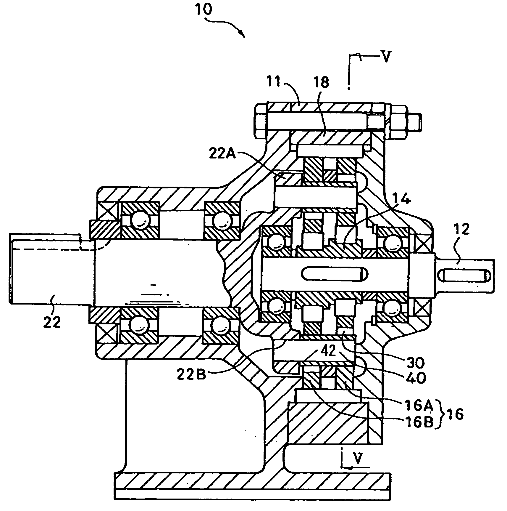
BACKGROUND OF THE INVENTION [0001] 1. Field of the Invention [0002] The present invention relates to a planetary reduction mechanism, a pin structure, and a method for manufacturing a pin used in the planetary reduction mechanism. [0003] 2. Description of the Related Art [0004] An oscillatingly internally meshing planetary gear reduction mechanism is widely known. The mechanism includes an internal gear and an external gear that internally meshes with the internal gear while oscillatingly moves. The mechanism prevents rotation of the external gear or takes out a rotational component thereof via an inner pin extending through the external gear. [0005] U.S. Pat. No. 4,898,065 discloses a planetary gear reducer device having a structure shown in FIGS. 4 and 5. [0006] The planetary gear reducer device 10 includes an input shaft 12, an eccentric body 14, two external gears 16 (16A and 16B), an internal gear 18 with which the external gears 16 internally mesh, and an output shaft 22 as ma...

Claims


Application Information

Patent Timeline
IPC IPC(8): F16H13/06F16H1/32F16H55/17F16H57/02F16H57/04
CPCF16H57/04F16H1/32
Inventor TSURUMI, YOHAGA, TAKASHITAMENAGA, JUN
Owner SUMITOMO HEAVY IND LTD
Learn More