Engine rotation condition detecting system and engine control method

a technology of condition detection and engine control, which is applied in the direction of valve details, valve arrangements, valve drives, etc., can solve the problems of inability to accurately detect low engine speed or stop position, inability of electromagnetic sensor pulse signal to detect reverse rotation, and inability to generate large induction voltage at low engine speed conditions. to achieve accurate detection of rotation condition and less cost

Inactive Publication Date: 2006-03-02
DENSO CORP
View PDF12 Cites 46 Cited by
  • Summary
  • Abstract
  • Description
  • Claims
  • Application Information

AI Technical Summary

Benefits of technology

[0010] It is therefore an object of the present invention to provide an engine rotation condition detecting system and an engine control method, which can accurately detect the rotation condition in less cost.
[0011] According to the present invention, an internal combustion engine has a variable valve timing control mechanism, in which a camshaft is driven by an electric motor. A motor rotation position sensor, which may be a Hall element type sensor, is provided to detect motor rotation positions. Rotation spee

Problems solved by technology

This electromagnetic sensor cannot generate large induction voltages at low engine speed conditions, which may occur right after the engine is started or immediately before the engine is stopped.
Therefore, low engine rotation speeds or stop position cannot be accurately detected based on the output signal of the electromagnetic sensor.
Further, although the engine s

Method used


Image

  • Engine rotation condition detecting system and engine control method
  • Engine rotation condition detecting system and engine control method
  • Engine rotation condition detecting system and engine control method

Examples


first embodiment

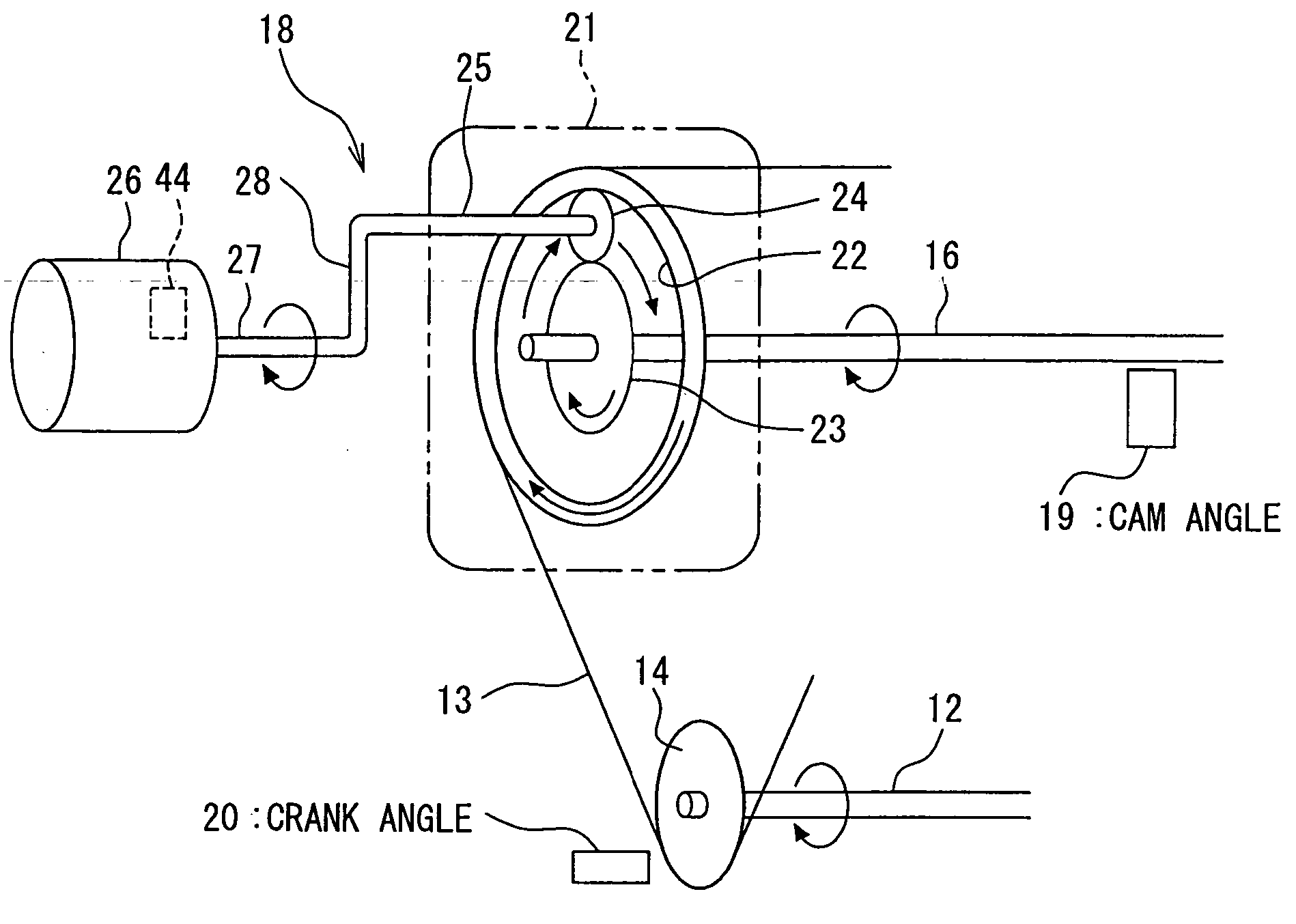
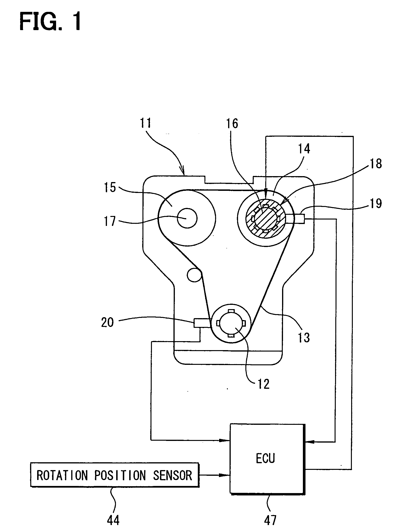
[0018] Referring first to FIG. 1, an internal combustion engine 11 has a crankshaft 12, an intake side camshaft 16 and an exhaust side camshaft 17. The camshafts 16 and 17 are coupled with the crankshaft 12 by a timing chain or belt 13 through respective sprockets 14 and 15 to be driven by the crankshaft 12. A motor-driven variable valve timing (VVT) apparatus 18 is provided on the intake side camshaft 16. The apparatus 18 varies the rotation phase (camshaft phase) of the intake side camshaft 16 relative to the crankshaft 12, so that the valve timing (open / close timing) of an intake valve (not shown) driven by the intake side camshaft 16 is varied.

[0019] A cam angle sensor 19 is provided near an outer periphery of the camshaft 16 to generate a cam angle signal at every predetermined cam angle rotation. A crank angle sensor 20 is provided near an outer periphery of the crankshaft 12 to generate a crank angle signal at every predetermined crankshaft angular rotation. The sensors 19 a...

second embodiment

[0039] In the second embodiment, the ECU 48 detects the engine rotation speed NE and the engine rotation direction based on the output signal (MPSO) of the motor rotation sensor 44 by controlling the rotation phase of the camshaft 16 to the most retarded or advanced position relative to the rotation phase of the crankshaft 12, when the rotation speed NE is low. The ECU 48 further detects the engine rotation stop position based on the output signal (MPSO) of the motor rotation sensor 44 when the engine 11 is stopped with the camshaft rotation phase being held controlled to the most retarded or advanced position.

[0040] Specifically, as shown in FIG. 5, the ECU 48 controls the camshaft rotation phase to the most retarded position (MRP) or most advanced position (MAP) at step 104a when the engine rotation speed NE is determined to be lower than the reference speed (Nref) at step 102. In this instance, the driving motor 26 is driven to move a movable part (not shown) of the VVT apparatu...


PUM


Abstract

An internal combustion engine has a variable valve timing apparatus including a driving motor between a crankshaft and a camshaft. The driving motor rotates synchronously with the camshaft when the valve timing apparatus is not in operation. A motor rotation sensor produces a motor rotation signal. When the engine rotation speed is below a reference speed, the driving motor is not energized. Under this condition, the rotation speed and the rotation direction of the engine are calculated based on the motor rotation signal in place of a crank rotation signal produced by a crank angle sensor. Further, the rotation stop position of the engine is calculated based on the motor rotation signal when the engine is stopped.

Description

CROSS REFERENCE TO RELATED APPLICATION [0001] This application is based on and incorporates herein by reference Japanese patent application No. 2004-253175 filed on Aug. 31, 2004. FIELD OF THE INVENTION [0002] The present invention relates to an engine rotation condition detecting system and an engine control method, which uses a rotation sensor of an electric driving motor of a variable valve timing apparatus. BACKGROUND OF THE INVENTION [0003] In engine control systems, as proposed in JP 60-240875, an engine rotation speed is detected based on an interval between pulse signals successively generated by a crank angle sensor during engine rotation. [0004] During engine rotation, cylinders are discriminated based on output signals of a crank angle sensor and a cam angle sensor indicative of crankshaft rotation angles (angular positions) and camshaft rotation angles (angular positions). Ignition timing and fuel injection are also controlled based on those output signals. When an engin...

Claims


Application Information

Patent Timeline
IPC IPC(8): F01L1/34
CPCF01L1/022F01L1/024F01L1/352F01L2820/041F01L2800/03F01L2820/032F01L2800/00
Inventor IZUMI, KAZUNARIURUSHIHATA, HARUYUKI
Owner DENSO CORP
Why Eureka
Try Eureka