Fuel injection system comprising a pressure intensifier and a delivery rate-reduced low-pressure circuit

Inactive Publication Date: 2006-03-02
ROBERT BOSCH GMBH
View PDF6 Cites 8 Cited by
  • Summary
  • Abstract
  • Description
  • Claims
  • Application Information

AI Technical Summary

Benefits of technology

[0005] According to the provisions of the invention, to reduce the prefeed quantity, the return from the pressure booster is not depressurized completely and pumped back into the fuel tank. As proposed, a compensation container can be integrated with the return from the pressure booster, and a return line can discharge into the low-pressure circuit, for instance directly downstream of the comp

Problems solved by technology

The use of a pressure boosting device in a fuel injection system that includes a common rail leads to a greatly increased fuel quantity demand per fuel injecto

Method used


Image

  • Fuel injection system comprising a pressure intensifier and a delivery rate-reduced low-pressure circuit
  • Fuel injection system comprising a pressure intensifier and a delivery rate-reduced low-pressure circuit
  • Fuel injection system comprising a pressure intensifier and a delivery rate-reduced low-pressure circuit

Examples


Example

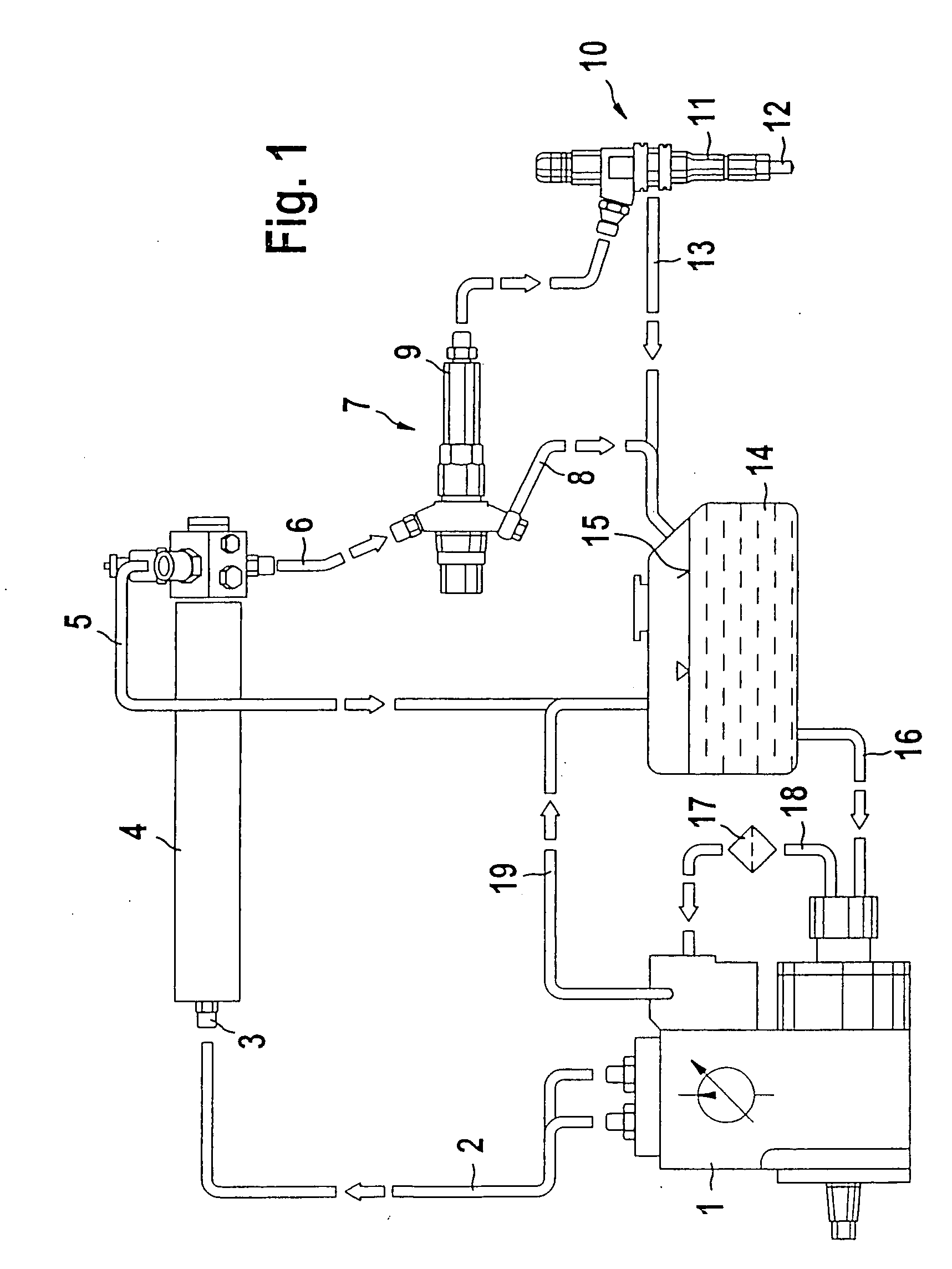
[0012]FIG. 1 shows the hydraulic interconnection of the components of a fuel injection system with a common rail and a pressure booster, along with the components used in it.

[0013] The fuel injection system with a high-pressure reservoir or common rail 4 and a pressure booster 7 upstream of a fuel injector 10 includes a high-pressure pumping unit 1. A metering unit, not shown in further detail, precedes the high-pressure pumping unit 1, and by way of it fuel is metered as needed to the high-pressure pumping unit. From a fuel tank 14, which contains fuel whose fuel level is shown at 15, fuel flows via an inlet 16 to a prefeed pump upstream of the high-pressure pumping unit 1. The fuel is compressed in that pump to the prefeed pressure. Next, the compressed fuel travels through a fuel filter 17 and is metered, controlled by demand, by a metering unit not shown in further detail to the high-pressure pumping unit 1. Control, scavenging and lubrication quantities are returned to the fue...


PUM


Abstract

A fuel injection system for an internal combustion engine, having a fuel injector supplied with fuel from a high-pressure fuel source and including an injection valve member for opening or closing injection openings and a low-pressure circuit with a prefeed pump which pumps fuel from a fuel tank. Partial return fuel quantities, depressurized to the prefeed pressure of the prefeed pump, are delivered to the low-pressure circuit by pressure boosters or by fuel injectors inside an infeed portion via returns.

Description

FIELD OF THE INVENTION [0001] For supplying combustion chambers of self-igniting internal combustion engines with fuel, both pressure-controlled and stroke-controlled injection systems can be employed. As fuel injection systems, not only unit fuel injectors and pump-line-nozzle units but also reservoir injection systems are also used. Reservoir injection systems (common rails) advantageously make it possible to adapt the injection pressure to the load and rpm of the engine. To attain high specific outputs, a high injection pressure is required. The higher the attainable injection pressure, the less are the emissions from the engine. BACKGROUND OF THE INVENTION [0002] German Patent Disclosure DE 199 10 970 A1 has a fuel injection system as its subject. This system has a pressure boosting unit, which is located between a pressure reservoir and a nozzle chamber and whose pressure chamber communicates with the nozzle chamber via a pressure line. A bypass line connected to the pressure r...

Claims


Application Information

Patent Timeline
IPC IPC(8): F02M57/02F02M47/02F02M59/10F02M63/00F02M63/02
CPCF02M47/027F02M57/025F02M59/105F02M63/0285F02M63/0043F02M63/0225F02M63/025F02M63/0015
Inventor MAGEL, HANS-CHRISTOPHGEYER, GERHARD
Owner ROBERT BOSCH GMBH
Why Eureka
Try Eureka