

Fibre optic laser machining equipment for etching grooves forming incipient cracks
- Summary
- Abstract
- Description
- Claims
- Application Information
AI Technical Summary
Benefits of technology
Problems solved by technology
Method used
Image

Examples
Embodiment Construction
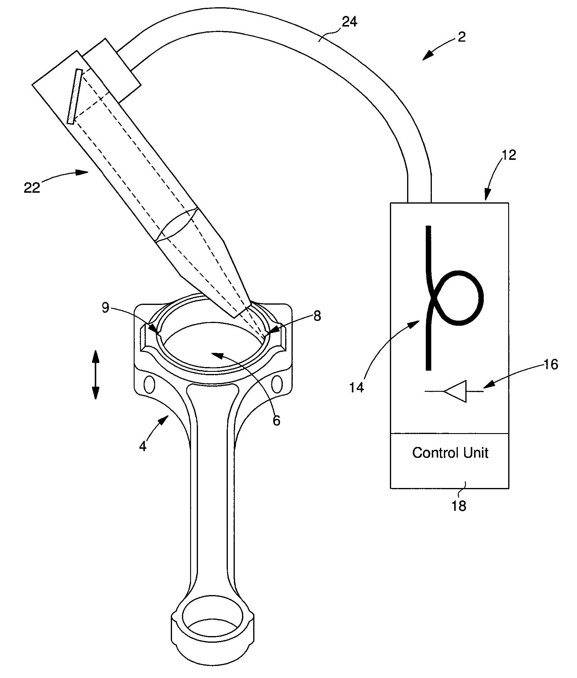
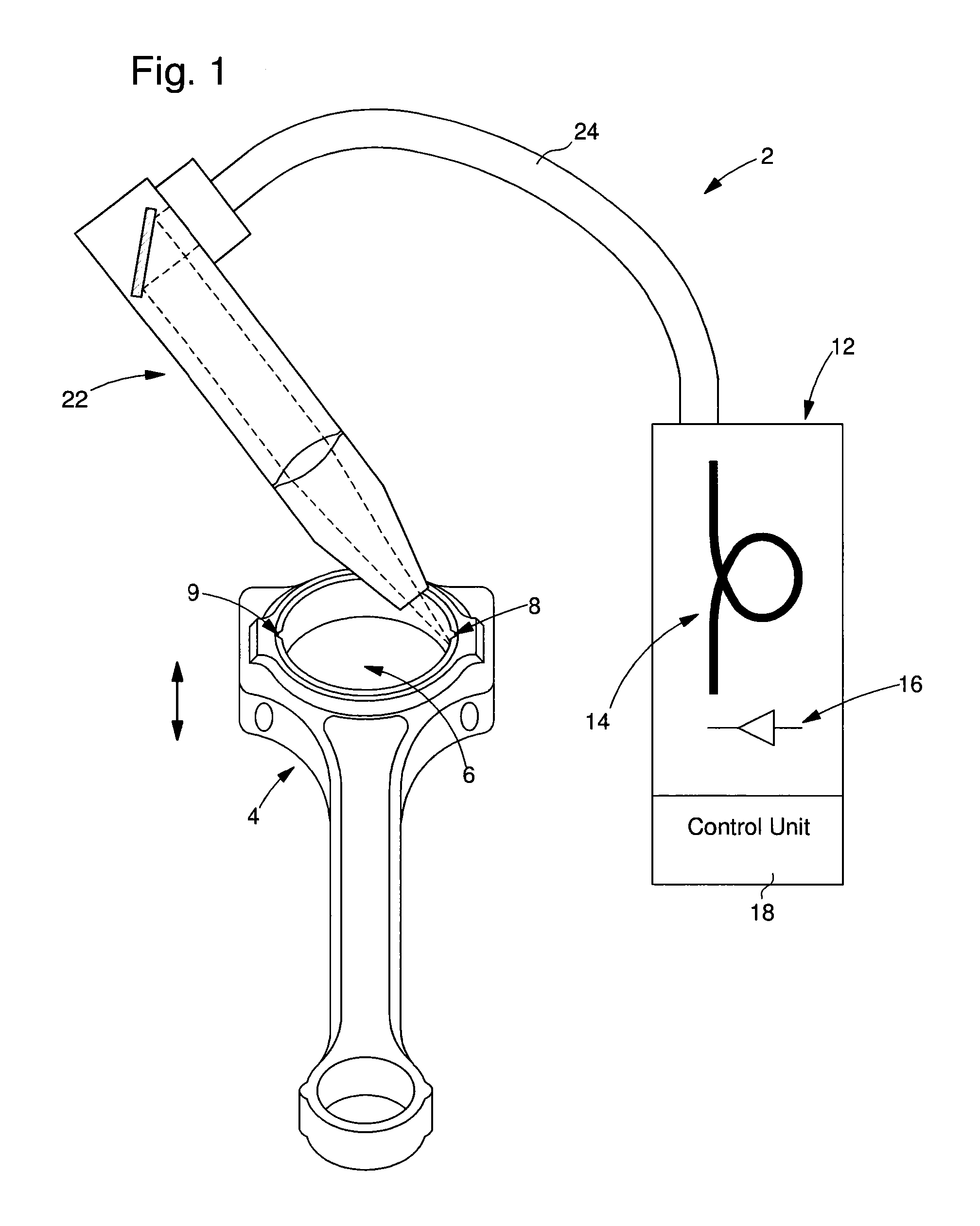
[0021]FIG. 1 is a schematic view of a laser machining equipment 2 for making grooves 8 and 9 in the lateral wall of the main aperture 6 of a connecting rod 4. These grooves are oriented along the central geometric axis of the main aperture. The equipment includes a fibre optic laser device 12 connected to a machining head 22 by a flexible optical cable 24. Machining head 22 and connecting rod 4 are associated with a motorised means (not shown) of relative movement along said central geometric axis for etching the grooves. Laser device 12 include an active fibre optic medium 14 known to those skilled in the art and a means 16 of pumping formed of optic diodes coupled to the active medium. This device includes a control unit 18 which controls the powering of the optical pumping means and other parameters according to the selected operating mode. Generally, a series of laser pulses is supplied.
[0022]The use of a fibre optic laser has several advantages relating to the quality of the la...
PUM
| Property | Measurement | Unit |
|---|---|---|
| Time | aaaaa | aaaaa |
| Time | aaaaa | aaaaa |
| Time | aaaaa | aaaaa |
Abstract
Description
Claims
Application Information