Ultrasonic optical cleaning system

a cleaning system and ultrasonic technology, applied in the direction of cleaning processes and apparatus, cleaning using liquids, instruments, etc., can solve the problems of user inconvenience, time-consuming and inefficient, and erroneous readings,

a cleaning system and ultrasonic technology, applied in the direction of cleaning processes and apparatus, cleaning using liquids, instruments, etc., can solve the problems of user inconvenience, time-consuming and inefficient, and erroneous readings,

US20060042671A1Inactive Publication Date: 2006-03-02HF SCI INC

Image

  • Ultrasonic optical cleaning system
  • Ultrasonic optical cleaning system
  • Ultrasonic optical cleaning system

Examples


Embodiment Construction

[0015] Other objects, features and advantages will occur from the following description of a preferred embodiment and the accompanying drawings, in which:

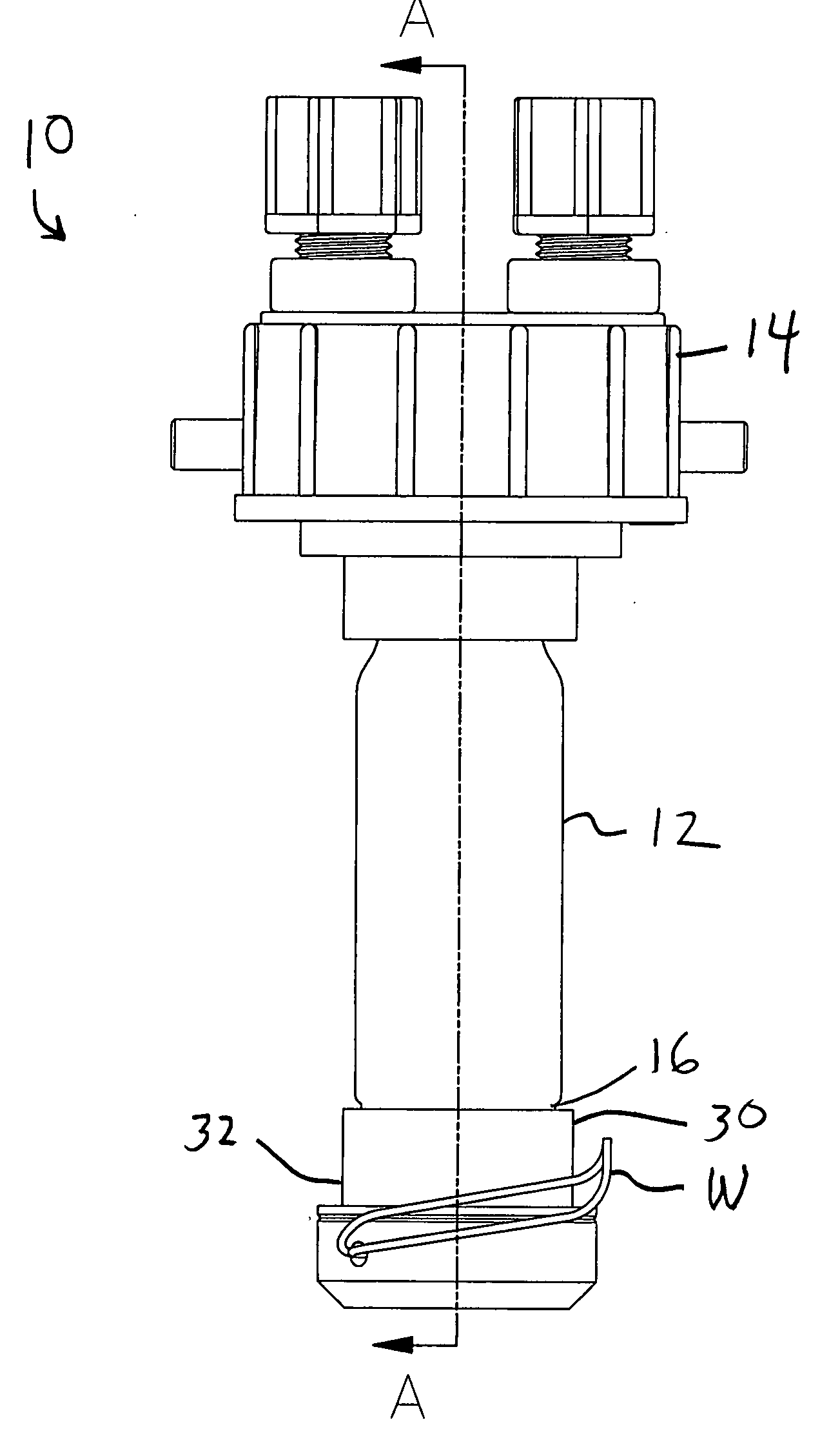
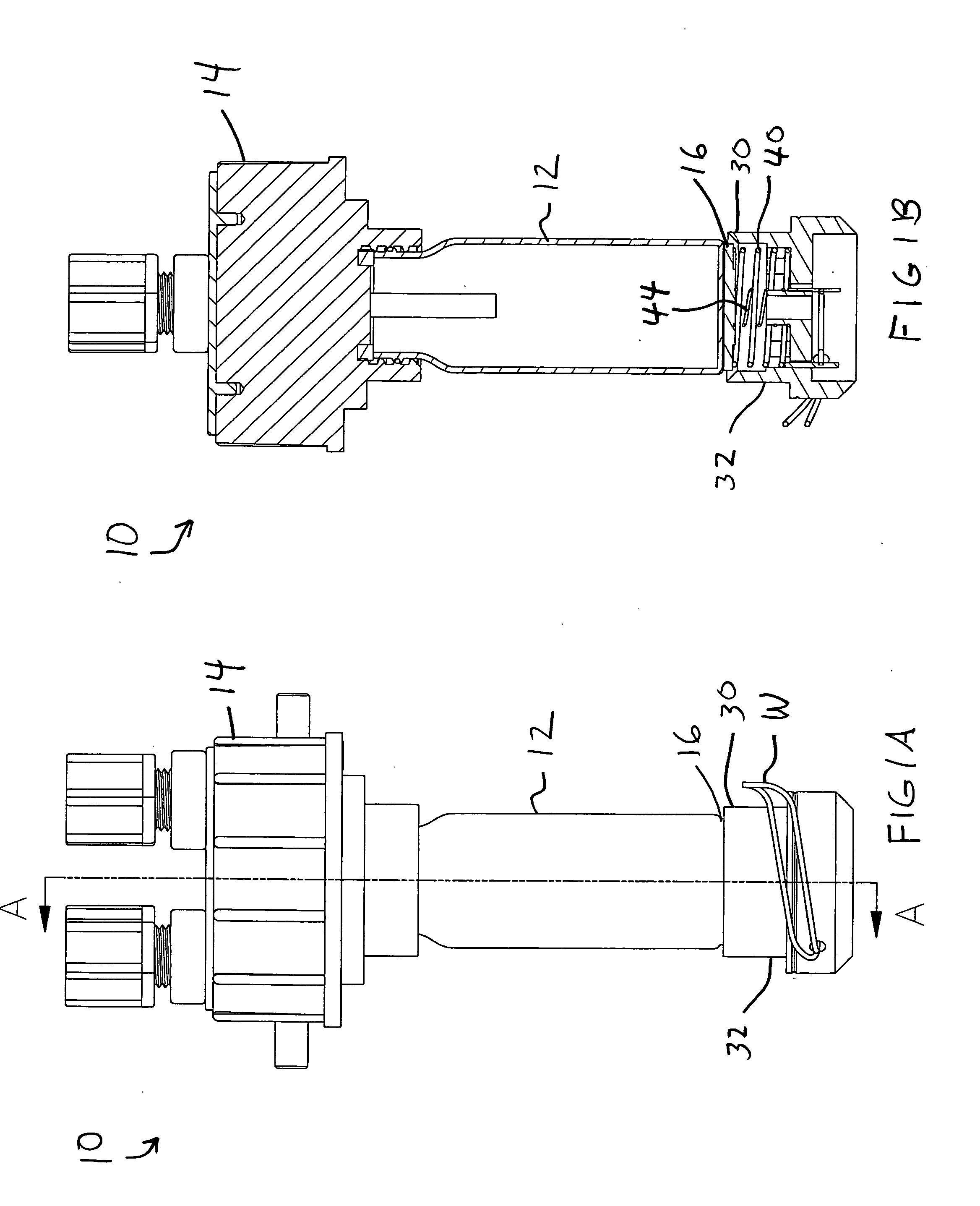
[0016]FIG. 1A is side elevational view of the ultrasonic optical cleaning system of this invention as used with a turbidimeter;

[0017]FIG. 1 B is a cross sectional view of the cleaning system;

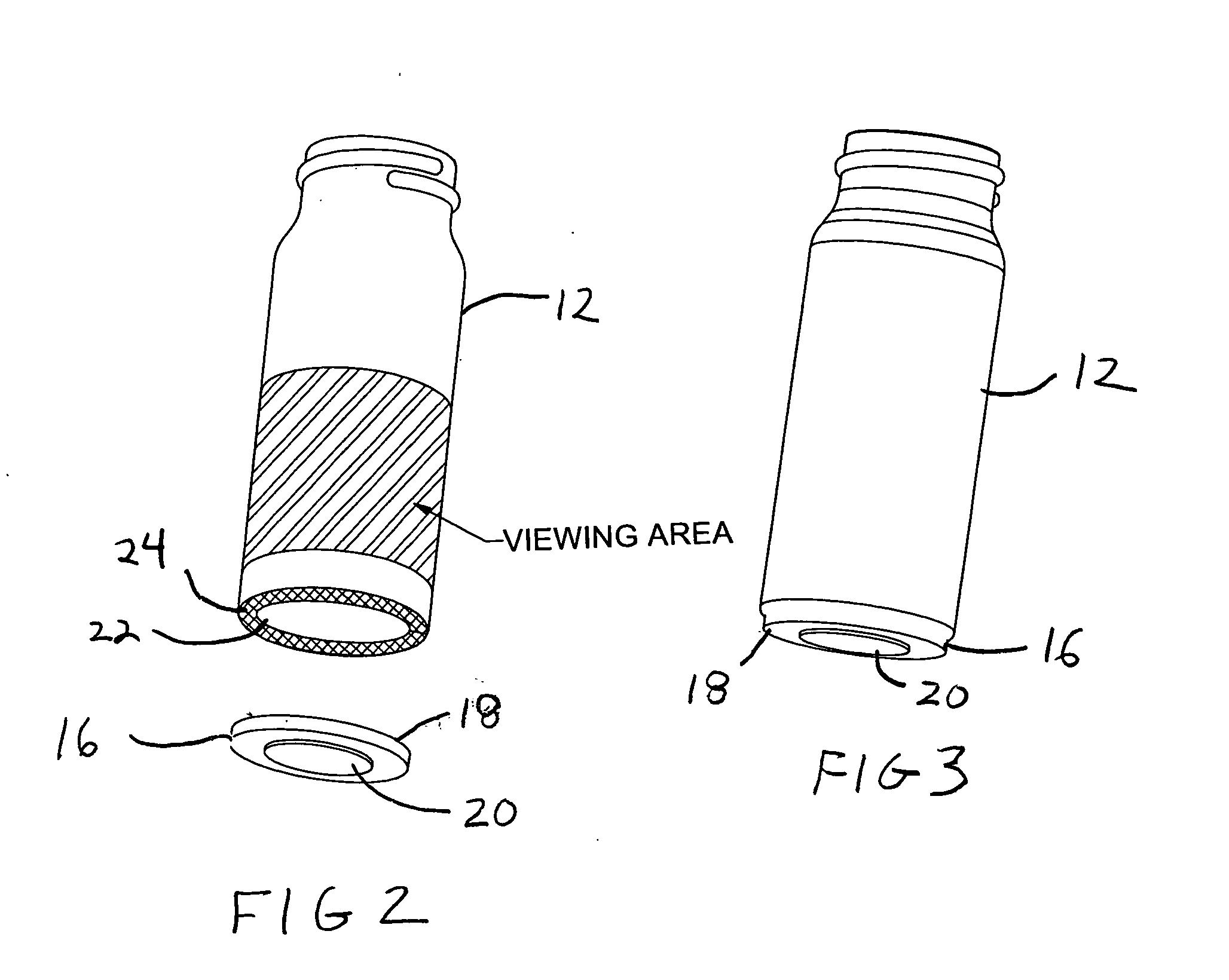
[0018]FIG. 2 is a perspective view of glassware comprising a cuvette and the ultrasonic transducer in position to be applied to the cuvette;

[0019]FIG. 3 is a view similar to FIG. 2 with the ultrasonic transducer bonded to a lower surface of glassware;

[0020]FIG. 4 is a perspective top view of the connector cap;

[0021]FIG. 4A is an exploded view of the connector cap;

[0022]FIG. 5 is a bottom perspective view of the connector cap;

[0023]FIG. 6 is a plan view of the upper, component side of the main printed circuit board employed in a turbidimeter featuring the cleaning system of this invention; the ultrasonic printed circuit board is depicted...


PUM


Abstract

An ultrasonic optical cleaning system is provided for cleaning and deterring the buildup of organic and inorganic particulates from the surface of glassware used in water testing instrumentation. The system includes a transducer that is attached to the surface of the glassware. A connector cap carrying a plurality of spring contacts interconnecting the transducer with an ultrasonic transducer control circuit. The control circuit operates continuously to provide an electrical signal to the transducer that vibrates the transducer and the glassware so that the glassware is cleaned of contaminates.

Description

RELATED APPLICATION [0001] This application claims the benefit of U.S. Provisional Patent Application Ser. No. 60 / 513,857 filed Oct. 24, 2003.FIELD OF THE INVENTION [0002] This invention relates to a system that ultrasonically cleans and deters the buildup of particulate matter on glassware of the type used in optical water testing equipment. The apparatus is particularly suited for use in cleaning a tube or cuvette that supports a water sample in a turbidimeter. BACKGROUND OF THE INVENTION [0003] Turbidimeters are widely utilized to test public water supplies for the presence of particulate matter suspended in the water. Examples of these instruments include the turbidimeter disclosed in U.S. Pat. No. 5,446,544, as well as the updated version distributed by HF Scientific, Inc. under the brand name MICRO TOL™. These and other varieties of turbidimeters typically employ a glass cuvette or tube that holds the water to be tested. Light is directed through the test sample and turbidity ...

Claims


Application Information

Patent Timeline
02 Mar 2006
Publication
US20060042671A1
IPC
B08B3/12
CPC
B08B3/12; B08B9/08; G01N2021/154; B08B2209/005; G01N21/15; B08B9/22
Inventors
CONNELLY, ROWAN T.; CONDON, PAUL