Thermoelectric device and method of manufacturing the same

a technology of thermoelectric devices and thermoelectric devices, which is applied in the direction of thermoelectric devices with peltier/seeback effects, thermoelectric devices, etc., can solve the problems of device inability to be used and the range in which the device can be used, and achieve the effect of preventing the reduction of thermal efficiency

Inactive Publication Date: 2006-03-02
KK TOSHIBA
View PDF4 Cites 12 Cited by
  • Summary
  • Abstract
  • Description
  • Claims
  • Application Information

AI Technical Summary

Benefits of technology

[0020] In the present invention, the conductive member is welded at positions on each of the electrodes, the positions corresponding to portions in which the thermoelectric elements are not placed. This prevents thermal efficiency from being decreased by a reduction of the contact areas between the thermoelectric elements and the conductive member, the reduction otherwise resulting from the deformation of the shapes of the welded portions.

Problems solved by technology

However, since the melting point of solder is approximately 150 to 300° C., the heat resistance of the thermoelectric device has to be approximately 150 to 300° C. The temperature range in which the device can be used is thus limited, and there has been a problem that the device cannot be used in a high temperature environment of 300° C. or more.

Method used


Image

  • Thermoelectric device and method of manufacturing the same
  • Thermoelectric device and method of manufacturing the same
  • Thermoelectric device and method of manufacturing the same

Examples


Embodiment Construction

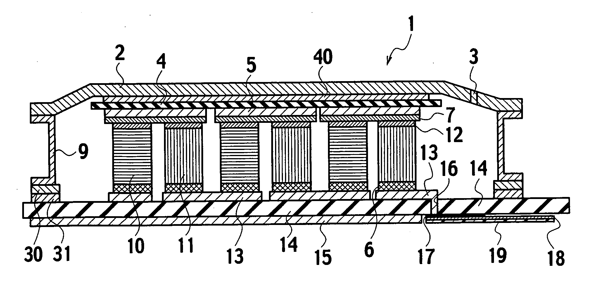
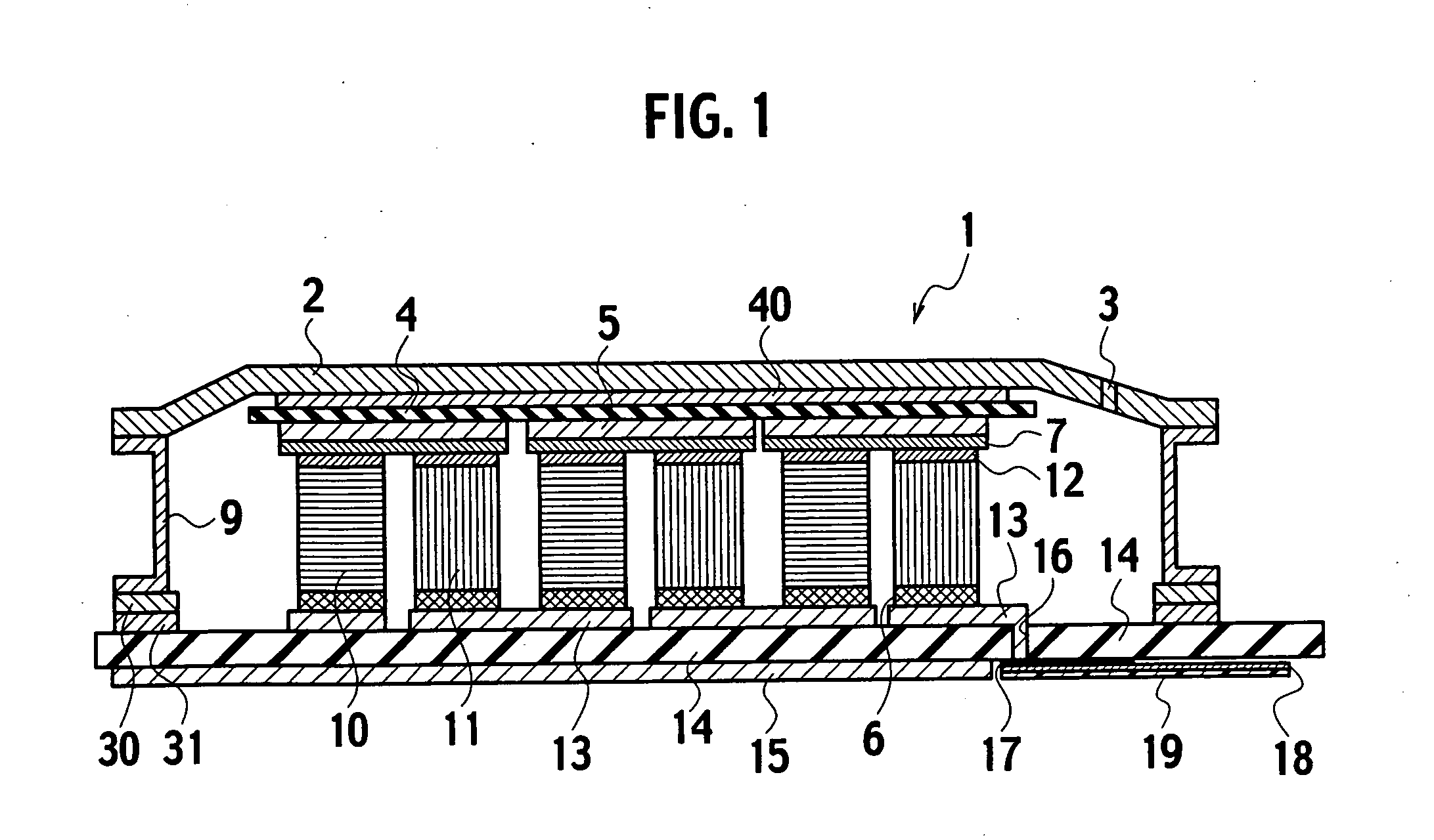
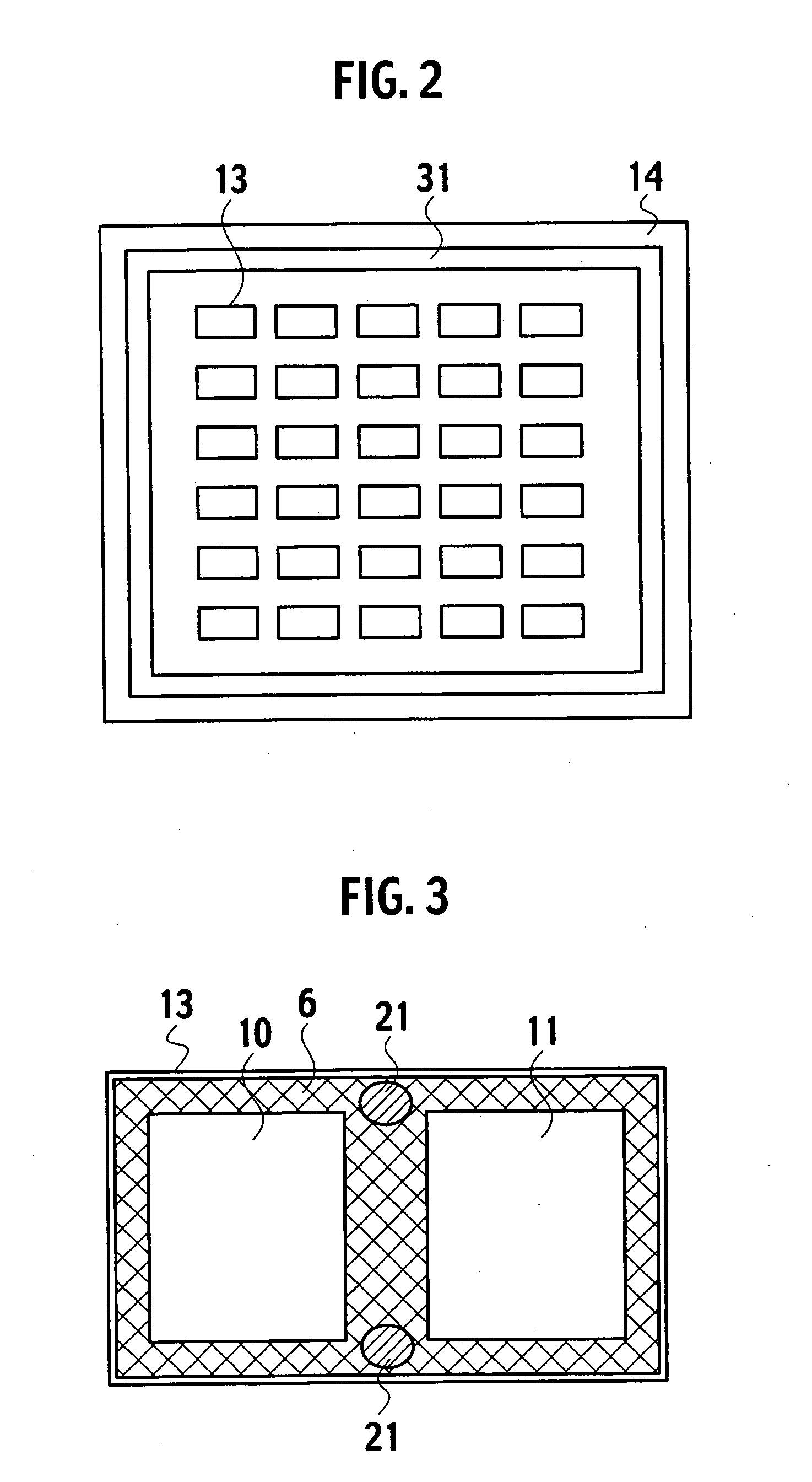
[0037] As shown in the cross-sectional view of FIG. 1, a thermoelectric device 1 of this embodiment has a first substrate 14 including a plurality of electrodes 13, a second substrate 4 including a plurality of electrodes 5, and a plurality of p-type thermoelectric elements 10 and a plurality of n-type thermoelectric elements 11 placed between these substrates. Each thermoelectric element 10 or 11 is placed so that one end thereof may correspond to an electrode 13 of the first substrate 14 and that the other end thereof may correspond to an electrode 5 of the second substrate 4. Electrodes 5 and 13 are arranged so that all of the thermoelectric elements 10 and 11 can be connected in series electrically. Further, the thermoelectric elements 10 and 11 are arranged in parallel thermally.

[0038] A surface of each electrode of the first substrates 14 or second substrates 4, one end of each thermoelectric element 10, and one end of each thermoelectric element 11 are plated with gold. In t...


PUM

PropertyMeasurementUnit
temperatureaaaaaaaaaa
heat resistanceaaaaaaaaaa
diametersaaaaaaaaaa

Abstract

In order to make a thermoelectric device usable in a high temperature environment of 300° C. or above, the necessity for solder is eliminated by bonding each electrode of a second substrate to one end of each thermoelectric element by using gold. Further, a conductive member, capable of accommodating expansion and contraction of the thermoelectric elements, is provided between each electrode of a first substrate, on which bonding by gold is not performed, and the other end of each thermoelectric element. Additionally, a lid is placed outside to the second substrate, and the lid and the first substrate are coupled so that pressure can be applied between the first and second substrates. Thus, the second substrate, the electrodes and the thermoelectric elements are held. This prevents the thermoelectric elements from being damaged due to thermal deformation as in the case where electrodes are bonded to thermoelectric elements by solder.

Description

CROSS-REFERENCE TO RELATED APPLICATIONS [0001] This application is based upon and claims the benefit of priority from Japanese Patent Application No. 2004-252838 filed on Aug. 31, 2004; the entire contents of which are incorporated herein by reference. BACKGROUND OF THE INVENTION [0002] 1. Field of the Invention [0003] The present invention relates to a thermoelectric device capable of performing conversion between heat and electricity. [0004] 2. Description of the Related Art [0005] Thermoelectric devices are devices utilizing thermoelectric effects, such as the Thomson effect, the Peltier effect, and the Seebeck effect. As temperature regulation units which convert electricity into heat, thermoelectric devices have been already put into mass production. Further, also as electric power generation units which convert heat into electricity, thermoelectric devices are being researched and developed. In a thermoelectric device, a plurality of thermoelectric elements are arranged betwee...

Claims


Application Information

Patent Timeline
Patent Type & Authority Applications(United States)
IPC IPC(8): H01L35/30H01L35/28
CPCH01L35/10H01L35/08H10N10/82H10N10/817H10N10/17
Inventor TATEYAMA, KAZUKISOGOU, TAKAHIROIGUCHI, TOMOHIROHANADA, HIROYOSHISAITO, YASUHITOARAKAWA, MASAYUKIKONDO, NARUHITO
Owner KK TOSHIBA
Why Eureka
Try Eureka