Manufacturing method and manufacturing apparatus of envelope

a manufacturing apparatus and manufacturing method technology, applied in the manufacture of electrode systems, electric discharge tubes/lamps, instruments, etc., can solve the problems of reducing the manufacturing time, generating a wasteful clearance (dead stroke) larger than the clearance for evacuating, and increasing the complexity of the manufacturing apparatus

Inactive Publication Date: 2006-03-02
CANON KK
View PDF11 Cites 49 Cited by
  • Summary
  • Abstract
  • Description
  • Claims
  • Application Information

AI Technical Summary

Benefits of technology

[0017] According to the manufacturing method of the envelope of the present invention, it is possible, just by warping the edge portions of one of the substrates, to generate a gap between the substrates or extend a clearance between them so as to evacuate a space between the substrates through the gap.
[0018] According to the manufacturing apparatus of the envelope of the present invention, it is possible, just by warping the edge portions of one of the substrates by the separating means, to generate a gap between the substrates or extend a clearance between them so as to evacuate a space between the substrates through the gap.

Problems solved by technology

In the case of the configuration for moving the entire substrate fixed on the position adjusting means with a fixture or the like in the direction for separating from the other substrate, however, it generates a wasteful clearance (dead stroke) larger than a sufficient clearance for evacuating a space between the substrates.
As for such a configuration generating the dead stroke, a manufacturing apparatus becomes more complicated and larger correspondingly and additional traveling time of the substrate is correspondingly required so that reduction in manufacturing time is interrupted.

Method used


Image

  • Manufacturing method and manufacturing apparatus of envelope
  • Manufacturing method and manufacturing apparatus of envelope
  • Manufacturing method and manufacturing apparatus of envelope

Examples


embodiments

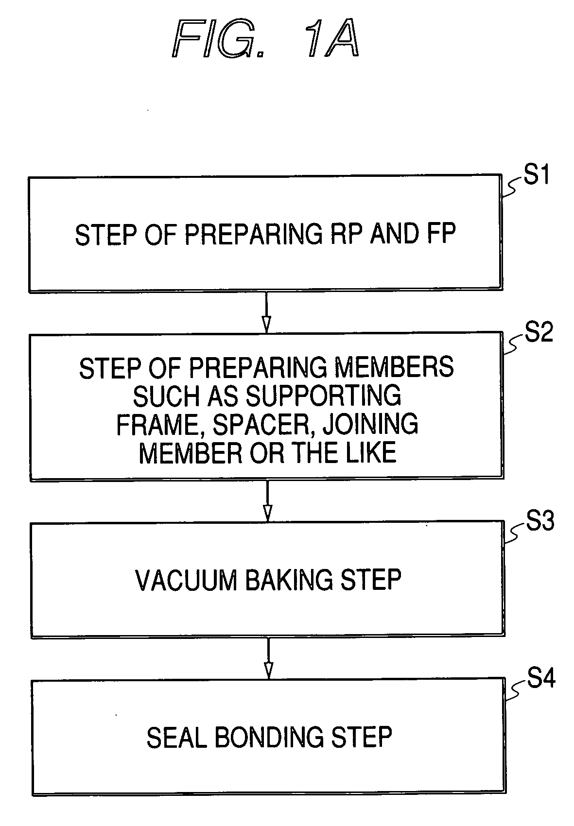
[0047] Hereunder, the manufacturing method of the envelope of the present invention will be described in detail by taking up concrete embodiments.

first embodiment

[0048] In this embodiment, the envelope was made by using a rear plate and a face plate both made of a blue plate glass of 900 mm×580 mm in length and breadth and 2.8 mm in thickness, spacers made of a blue plate glass of 1 mm×1 mm in length and breadth and 0.5 mm in thickness, and a supporting frame of 900 mm×580 mm in length and breadth with a surrounding wall of 4 mm in breadth and 0.2 mm in height (thickness). Raw glass substrates having no electron-emitting device, phosphor film or getter formed thereon were used for the rear plate and face plate respectively. The spacers were placed with 30-mm pitches. In was applied to the joining portions of the plates and the supporting frame.

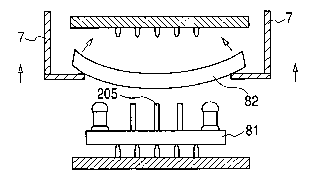
[0049] The temperature during the vacuum baking process was 200 degrees C. During that time, the positions at 5 mm from the corners of the face plate as the upper plate were supported by the arms, and the face plate was lifted to the height of 3 mm from the top surfaces of the spacers placed on the re...

second embodiment

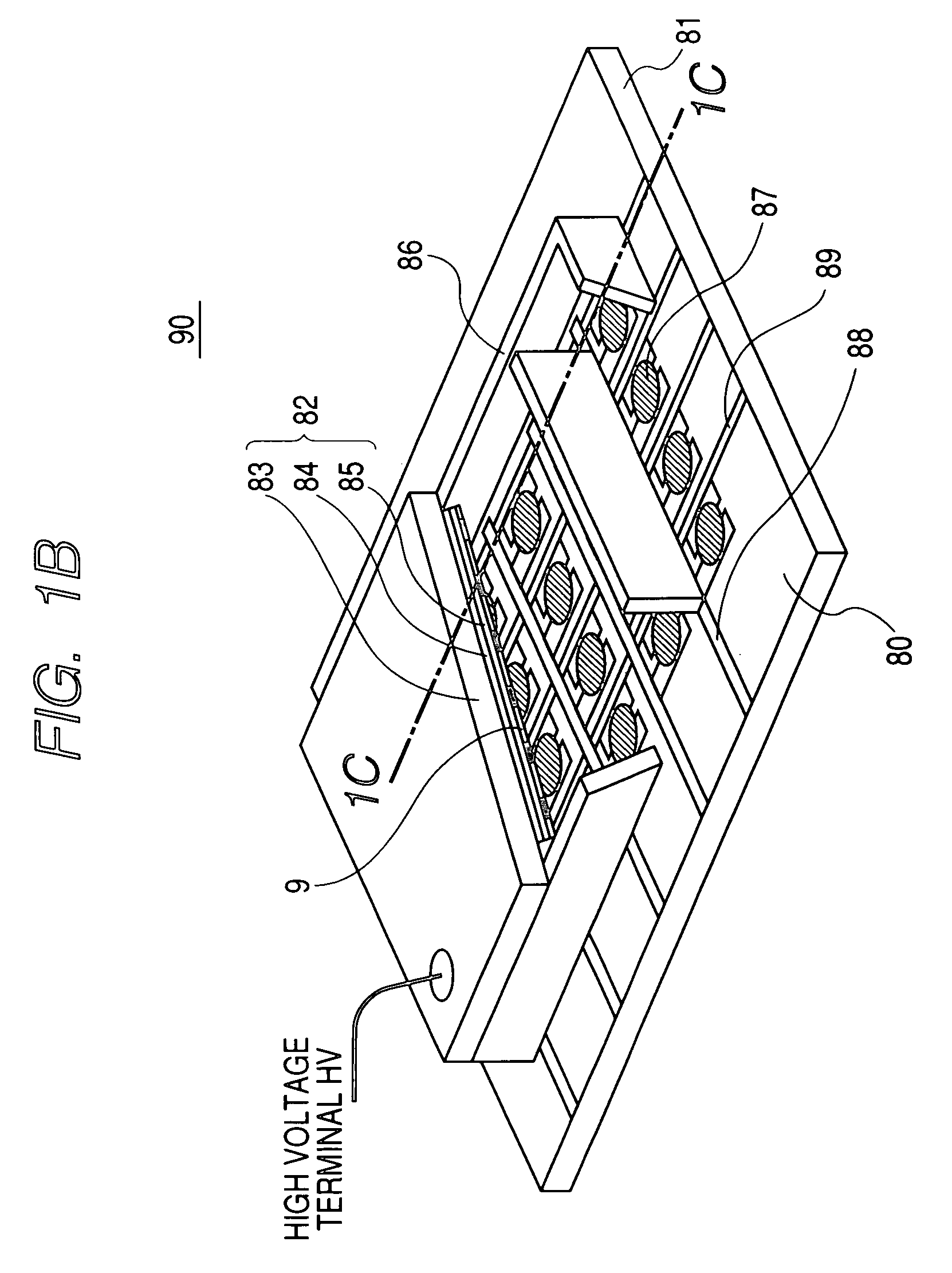
[0050] To give a description of this embodiment by referring to FIGS. 1A to 1C, the envelope as an image displaying apparatus was made by using the rear plate 81 having an SiO2 film of 3000 Å (300 nm) in thickness formed and electron-emitting devices and wirings further formed on the plate made of PD-200 (Asahi Glass Co., Ltd.) which is electric glass of 900 mm×580 mm in length and breadth and 2.8 mm in thickness, the face plate 82 having the phosphor film 84 and getter 9 formed on the plate made of PD-200 (Asahi Glass Co., Ltd.) which is electric glass of 900 mm×580 mm in length and breadth and 2.8 mm in thickness, the supporting frame 86 made of the blue plate glass of 830 mm×510 mm in length and breadth with a surrounding wall of 4 mm in breadth and 1.3 mm in thickness, and the spacers 205 having an antistatic film (not shown) formed on a surface of PD-200 (Asahi Glass Co., Ltd.) which is the electric glass of 780 mm in length and 200 μm in breadth and 1.6 mm in height. In was us...


PUM

PropertyMeasurementUnit
thicknessaaaaaaaaaa
thicknessaaaaaaaaaa
circumferencesaaaaaaaaaa

Abstract

In a manufacturing method of forming a hermetically sealed container by bringing a pair of substrates into intimate contact via a supporting frame between them, one of the substrates is warped in a depressurized atmosphere before getting into intimate contact and is thereby separated from the other substrate so as to evacuate inside of the hermetically sealed container by releasing the depressurized atmosphere therein. Relative positions of the substrates are restored by having the warp undone thereafter. Therefore, it is possible to achieve evacuation inside the hermetically sealed container without causing the relative positions of the substrates to deviate.

Description

BACKGROUND OF THE INVENTION [0001] 1. Field of the Invention [0002] The present invention relates to a manufacturing method and a manufacturing apparatus of an envelope of an image displaying apparatus and so on. [0003] 2. Related Background Art [0004] Japanese-Patent Application Laid-Open No. S06-196094 discloses a manufacturing method of a vacuum displaying apparatus with a glass container having display surface glass and substrate glass deposited with low melting glass, the method comprising stages of assembling the glass container having low melting point rod glass placed between display glass and the substrate glass, evacuating internal air of the glass container from a gap provided thereon, and melting and seal-bonding the low melting point rod glass in a state of remaining evacuated as-is. [0005] Japanese Patent Application Laid-Open No. 2001-28241 discloses a manufacturing method of an image displaying apparatus of seal-bonding via a joining member a first substrate having p...

Claims


Application Information

Patent Timeline
Patent Type & Authority Applications(United States)
IPC IPC(8): B29C65/00B32B37/00
CPCC03B23/0252C03B23/0258C03B35/202H01J2329/00C03C27/10H01J9/261H01J9/385C03C27/06
Inventor HASEGAWA, MITSUTOSHIHIMEJI, TOSHIAKI
Owner CANON KK
Why Eureka
Try Eureka