Pneumatic lifting system and method

a pneumatic and lifting technology, applied in the field of lifts, can solve the problems of limited lift capacity, more expensive manufacturing, and more prone to failure, and achieve the effects of less manufacturing or maintenance, less prone to failure, and convenient operation

Active Publication Date: 2006-03-02
COSSE III IRVY E +1
View PDF15 Cites 11 Cited by
  • Summary
  • Abstract
  • Description
  • Claims
  • Application Information

AI Technical Summary

Benefits of technology

[0021] Finally, it is an object of the present invention to provide a false bottom rolling planter which may be selectively lowered to fixed stationary position or lifted to a wheeled, positionable orientation which is easier to implement, more effective in operation, and less expensive to manufacture or maintain than prior art systems.

Problems solved by technology

These mechanical devices would tend to have limited lift capacity, are generally more expensive to manufacture, require maintenance and upkeep, and would appear to be more prone to failure when compared to the system of the present invention.

Method used


Image

  • Pneumatic lifting system and method
  • Pneumatic lifting system and method
  • Pneumatic lifting system and method

Examples


Embodiment Construction

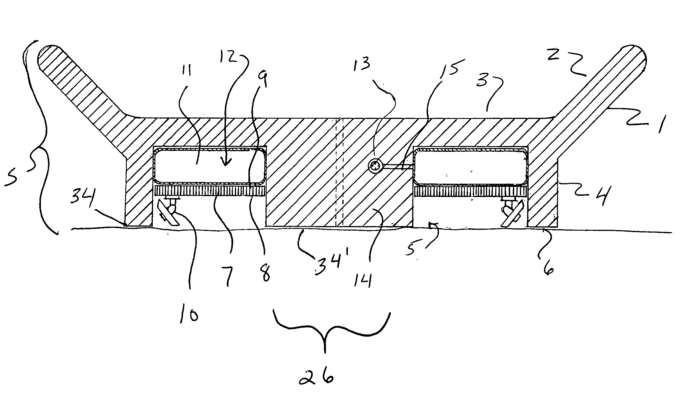
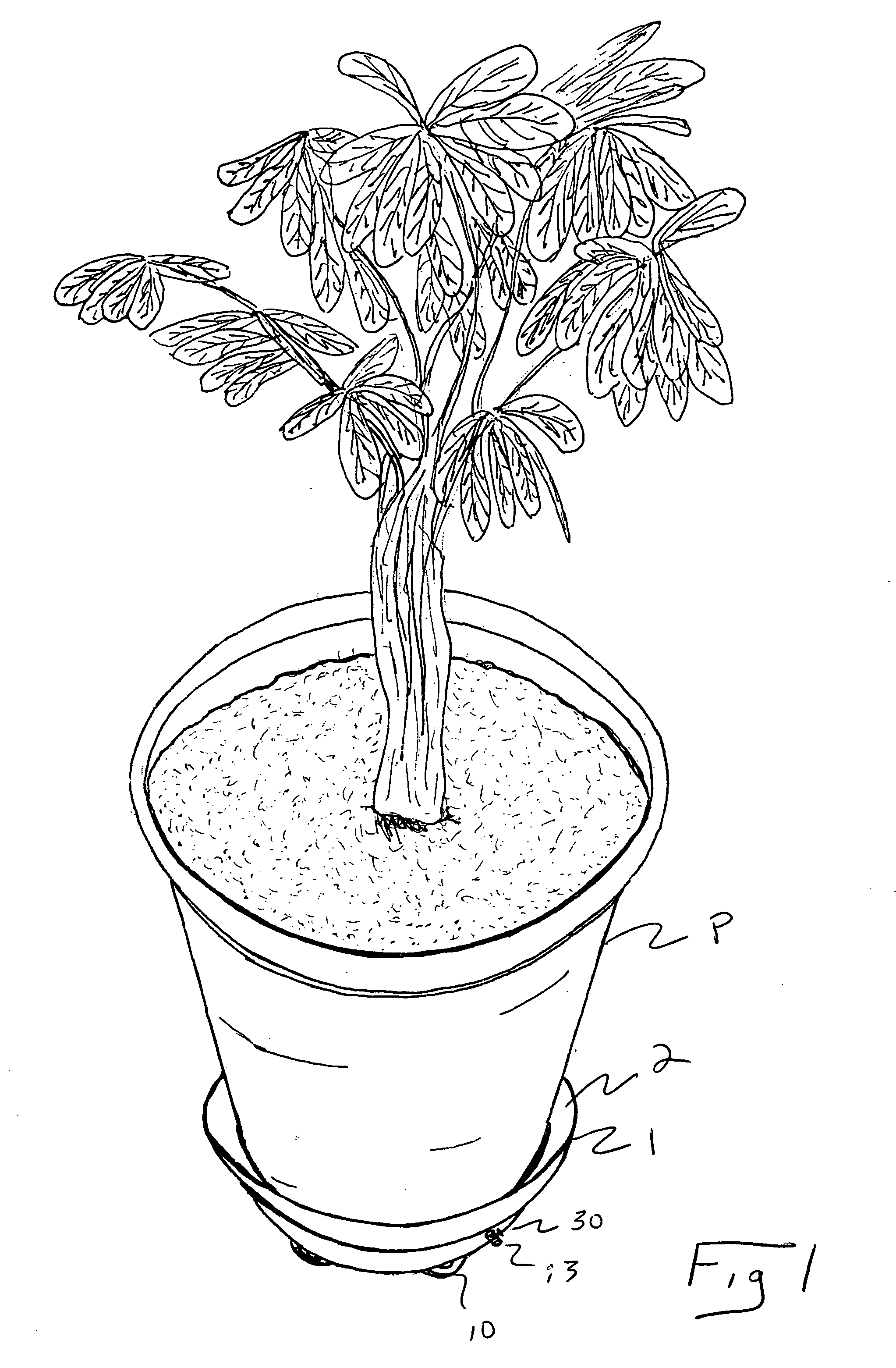
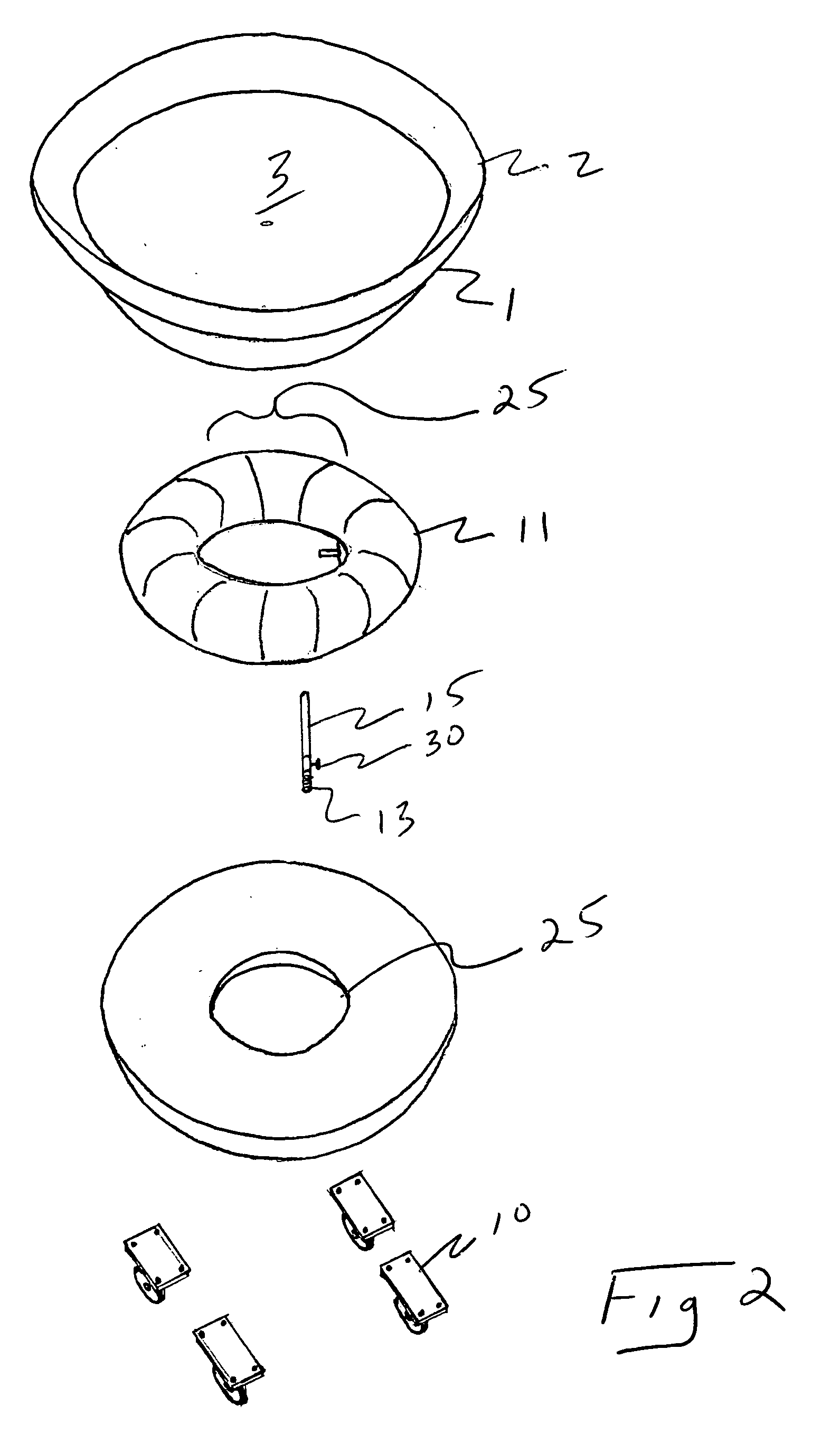
[0029] Referring to FIGS. 1, 2 and 3 of the drawings, the system S of the preferred embodiment of the present invention utilizes a uniquely designed and configured drain bowl 1 for receiving a plant pot P or the like thereupon to form a planter, the drain bowl 1 having an upper raised edge 2 about its perimeter to form a catch basin about the pot thereon, the pot P supported upon the bowl 1 via the support surface 3, so that the raised edge envelopes the lower portion of the pot when situated upon the support surface 3 to catch any water flowing therefrom.

[0030] Further provided in the drain bowl 1 is a base 4 having a cavity 5 formed therein, the base 4 having a lower edge formed to selectively engage the ground via a lift structure situated within the cavity 5 formed in the base 4, as will be more fully explained herein.

[0031] As shown, a lift platform 7 having upper 8 and lower 9 surfaces is situated within cavity 5, the lift platform having engaged to the lower 9 surface a set...


PUM


Abstract

A lifting device and method therefore utilizing an air bag or the like for lifting an object supported by a wheeled platform or the like, from a stationary, parked configuration wherein the object conceals the wheeled platform and supports the object, to a lifted, configuration whereby the wheeled platform supports the object, allowing same to be easily moved via the wheeled platform. The preferred embodiment of the present invention contemplates a planter unit comprising a pot or the like for containing a plant, said pot having a false bottom wherein there is situated a support platform having castors or the like thereon, and an air bag or other flexible container configured to be filled with fluid situated between the wheeled platform and the underside of the pot. In use, the false bottom has a cavity formed therein to enclose the wheeled platform, the false bottom having a lower edge supporting the pot when the air bag is uninflated. To lift the pot and raise the lower edge of the false bottom from the floor, the air bag or the like is filled with air via a hand pump or compressed air source, which expands the bag so as to lift the planter such that the wheeled support then supports the planter. The walls forming the false bottom surround the air bag in its inflated condition, stabilizing the unit so that it may be wheeled to its desired location, and preventing “rolling” of the airbag and planter from the platform.

Description

TECHNICAL FIELD OF THE INVENTION [0001] The present invention relates to lifts for lifting objects, and more particularly to a lifting device utilizing an air bag or the like for lifting an object supported by a wheeled platform or the like, from a stationary, parked configuration wherein the device conceals the wheeled platform and supports the object, to a lifted, configuration whereby the wheeled platform supports the object, allowing same to be easily moved via the wheeled platform. [0002] The preferred embodiment of the present invention contemplates a planter unit comprising a pot or the like for containing a plant, said pot having a false bottom wherein there is situated a support platform having castors or the like thereon, and an air bag or other flexible container configured to be filled with fluid situated between the wheeled platform and the underside of the pot. [0003] In use, the false bottom has a cavity formed therein to enclose the wheeled platform, the false bottom...

Claims


Application Information

Patent Timeline
Patent Type & Authority Applications(United States)
IPC IPC(8): B66B9/02
CPCA47G7/041B62B2205/14B62B5/0083
Inventor COSSE, IRVY E. IIIWHITESIDE, STEVEN E.
Owner COSSE III IRVY E
Why Eureka
Try Eureka