Electronic equipment rack

a technology for electronic equipment and racks, applied in the field of electronic equipment racks, can solve the problems of large space consumption, lack of substantial (and expensive) reinforcement, and inability to effectively stand up to seismic events, and achieve the effects of convenient routing, compact space preservation, and economical manufacturing

Inactive Publication Date: 2006-03-02
COOPER TECH CO
View PDF71 Cites 56 Cited by
  • Summary
  • Abstract
  • Description
  • Claims
  • Application Information

AI Technical Summary

Benefits of technology

[0003] Among the several objects of this invention may be noted the provision of an improved two-post electronic equipment rack for holding telecommunications equipment and the like; the provision of such a rack which, in at least one embodiment, is designed to withstand seismic events; the provision of such a rack which, in at least one embodiment, is relatively compact to preserve space; the provision of such a rack which, in at least one embodiment, is relatively lightweight (e.g., about 100 lbs) yet capable of holding a relatively heavy load of equipment (e.g., up to 1000 lbs); the provision of such a rack which, in at least one embodiment, is economical to manufacture; and the provision of such a rack which, in at least one embodiment, permits cable to be conveniently routed to and from the equipment on the rack.

Problems solved by technology

Conventional two-post racks typically occupy less space but they are not as effective in withstanding seismic events absent substantial (and expensive) reinforcement.
Cabinets, on the other hand, are generally more durable during seismic activity but consume large amounts of space, since the centerline spacing between the front and back posts is typically greater than 18 in.

Method used


Image

  • Electronic equipment rack
  • Electronic equipment rack
  • Electronic equipment rack

Examples


Embodiment Construction

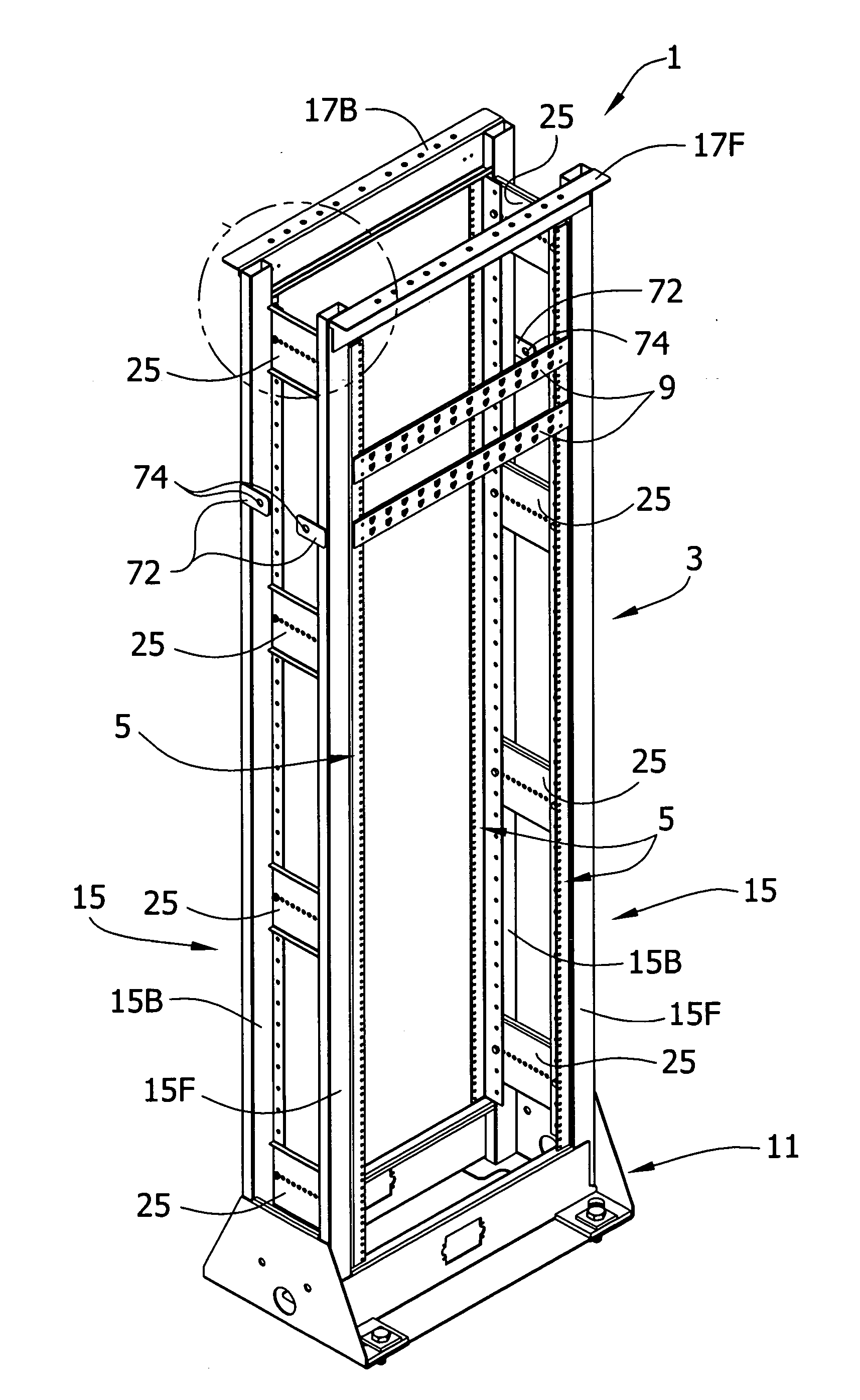
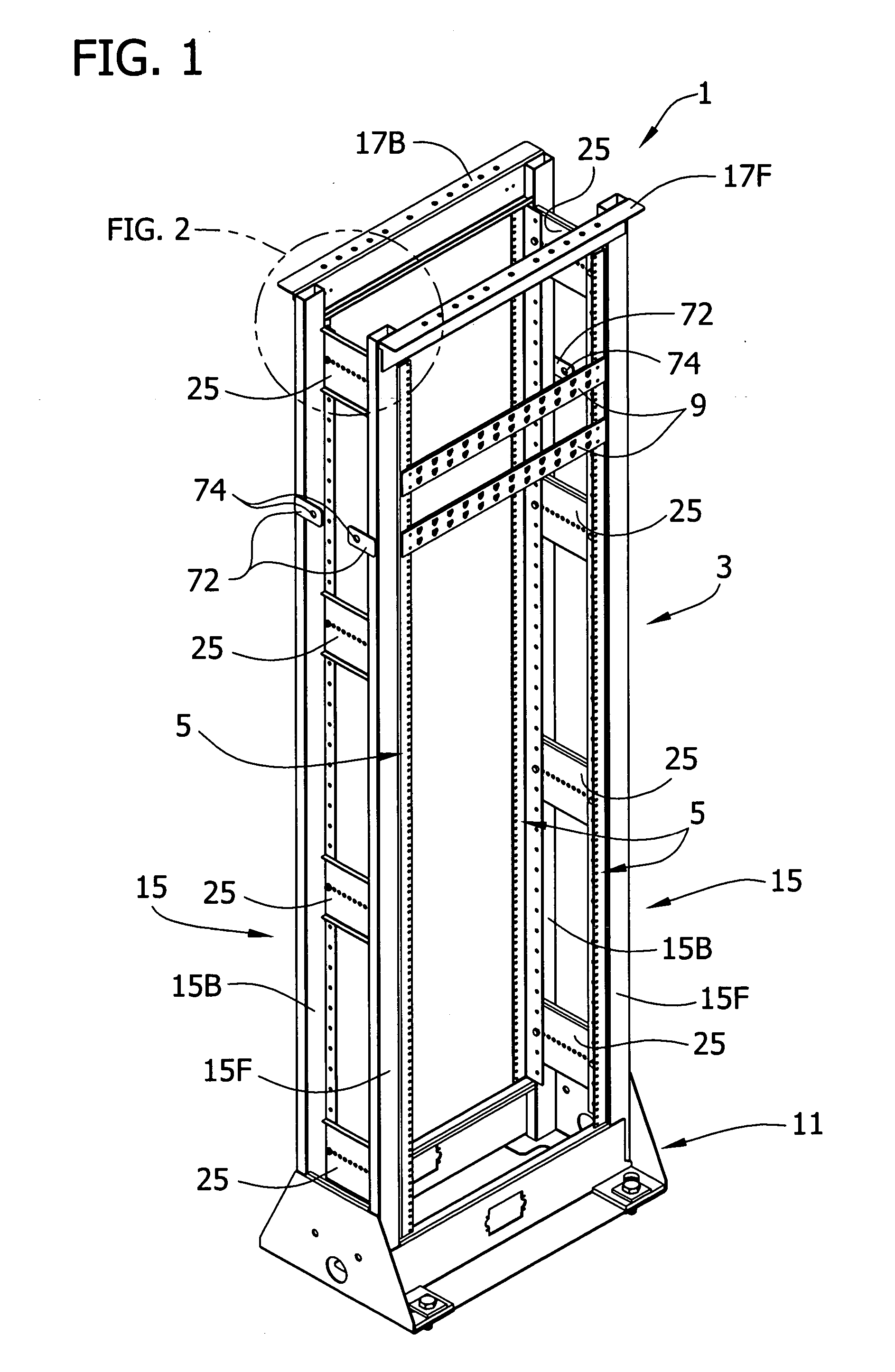
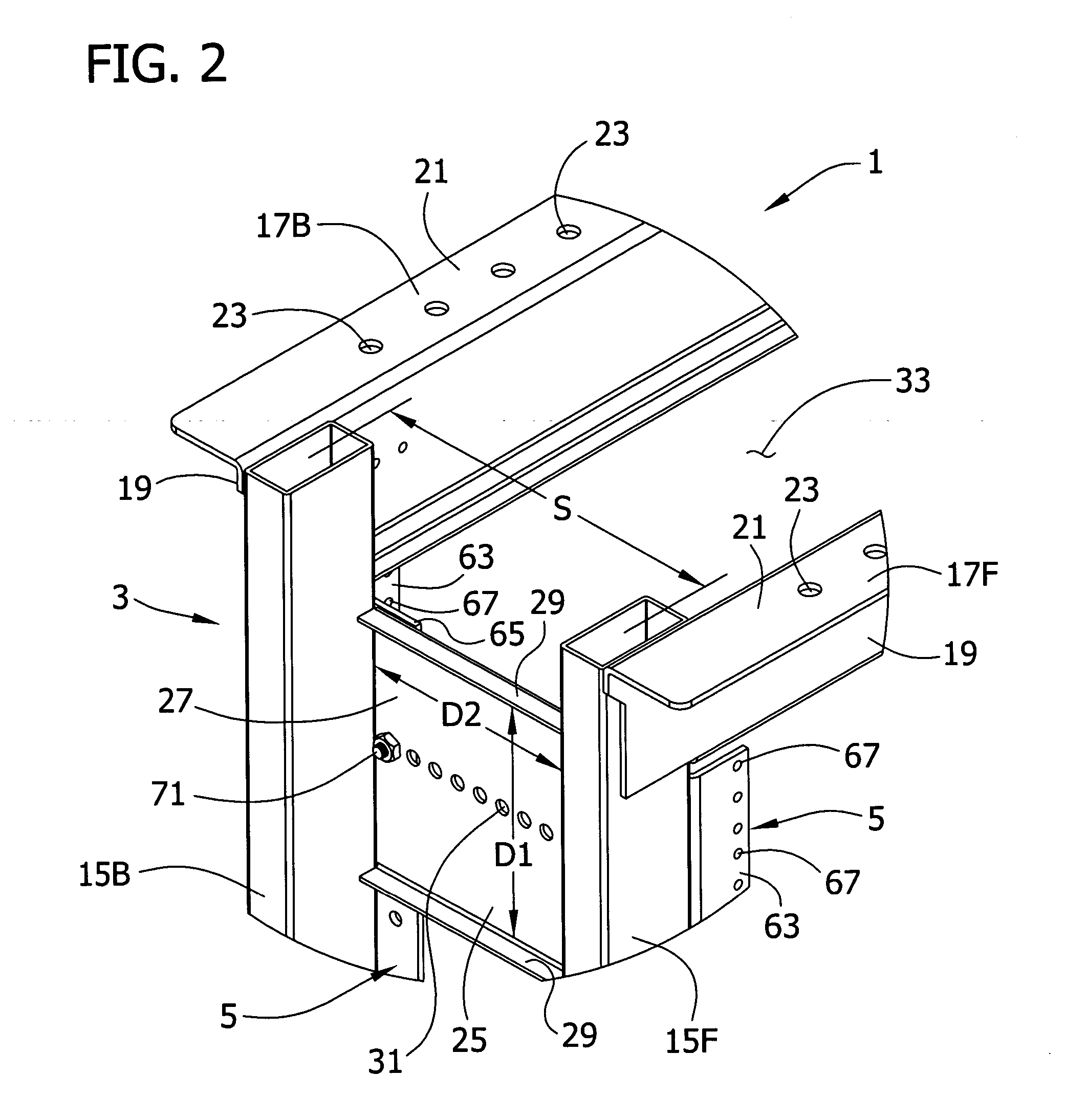
[0023] Referring to FIG. 1 of the drawings, one embodiment of a two-post electronic equipment rack of this invention is designated in its entirety by the reference numeral 1. In general, the rack 1 comprises a structural frame, generally indicated at 3, and a plurality of non-structural substantially vertical equipment mounting rails, each designated 5, attached to the structural frame for mounting electronic equipment 9 on the rack. The electronic equipment 9 illustrated in FIG. 1 is telecommunications equipment (e.g., patch panels), but it will be understood that the rack 1 is suitable for mounting other types of equipment as well.

[0024] The structural frame 3 includes a base, generally designated 11, and a pair of left and right posts, each generally designated 15, secured to the base and extending up from the base adjacent opposite sides of the base. Each of the posts 15 comprises front and back substantially vertical tubular frame members 15F, 15B. As used herein, a frame memb...


PUM


Abstract

A two-post electronic equipment rack of this invention is adapted for holding telecommunication equipment and the like. The rack comprises a structural frame including a base and a pair of posts secured to the base and extending up from the base adjacent opposite sides of the base. Each of the posts comprises substantially vertical front and back tubular frame members having a centerline spacing of less than about twelve in. The structural frame also includes a plurality of cross braces connecting the front and back tubular frame members of each of the two posts. A plurality of substantially vertical equipment mounting rails not constituting part of the structural frame are attached to the structural frame for mounting the equipment on the rack.

Description

BACKGROUND OF THE INVENTION [0001] This invention relates generally to electronic equipment racks, and particularly to such racks that are adapted to withstand seismic events. [0002] Racks for holding electronic equipment, such as telecommunications equipment, come in various configurations. Some racks, referred to as “two-post” racks, include a pair of upright posts, one at each side of the rack. Other racks, referred to as cabinets, include four upright posts, two toward the front of the rack at opposite sides of the rack and two toward the back of the rack at opposite sides of the rack. Typical cabinets have side panels extending between the front and back posts at opposite sides of the cabinet. Conventional two-post racks typically occupy less space but they are not as effective in withstanding seismic events absent substantial (and expensive) reinforcement. Cabinets, on the other hand, are generally more durable during seismic activity but consume large amounts of space, since ...

Claims


Application Information

Patent Timeline
Patent Type & Authority Applications(United States)
IPC IPC(8): A47F7/00
CPCH05K7/186
Inventor RINDERER, ERIC R.
Owner COOPER TECH CO
Why Eureka
Try Eureka