Optical encoding that utilizes total internal reflection

an optical encoding and internal reflection technology, applied in the field of optical encoding that utilizes total internal reflection, can solve the problems of limiting the profile dimension low signal, restricting the speed and resolution of the encoding system, etc., and achieves a small profile dimension. , good contrast

an optical encoding and internal reflection technology, applied in the field of optical encoding that utilizes total internal reflection, can solve the problems of limiting the profile dimension low signal, restricting the speed and resolution of the encoding system, etc., and achieves a small profile dimension. , good contrast

US20060043271A1Active Publication Date: 2006-03-02AVAGO TECH INT SALES PTE LTD

Image

  • Optical encoding that utilizes total internal reflection
  • Optical encoding that utilizes total internal reflection
  • Optical encoding that utilizes total internal reflection

Examples


Embodiment Construction

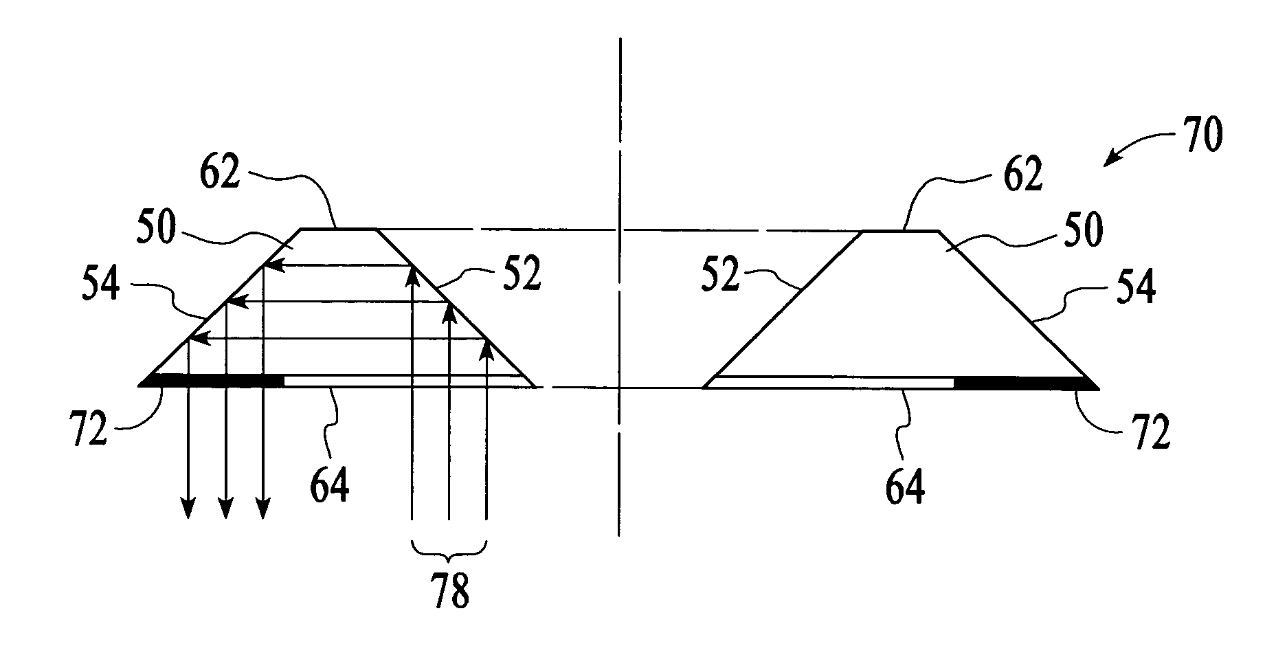
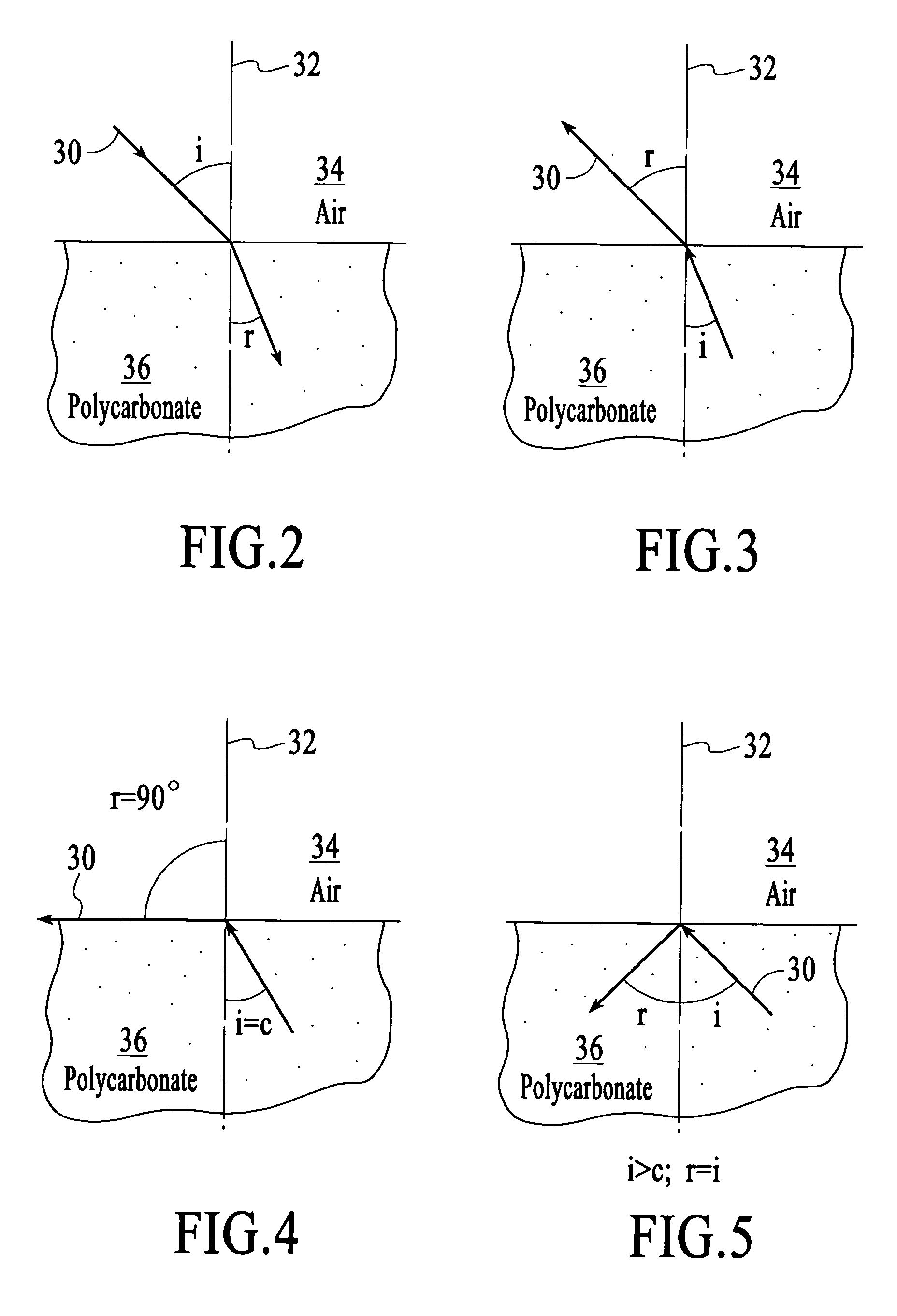
[0022] Total internal reflection (TIR) is a special phenomenon in optical refraction. When light travels from a low-density medium to a high-density medium, for example, from air to polycarbonate, it will refract towards the normal plane of the intercept point. FIG. 2 depicts the refraction of light 30 towards the normal plane 32 of the intercept point when light travels from a low-density medium 34 (e.g., air, with a refractive index of 1) to a high-density medium 36 (e.g., polycarbonate, with a refractive index of n). In FIG. 2, the light travels in air at an angle, i, relative to normal and then travels in the polycarbonate at an angle, r, relative to normal. The relation of the two angles, i and r, is governed by Snell's law as: sin⁢ ⁢isin⁢ ⁢r=n

[0023] When light travels instead from a high-density medium 36 (e.g., polycarbonate) to a low-density medium 34 (e.g., air), the light 30 refracts away from the normal plane. FIG. 3 depicts the refraction of light away from the normal p...


PUM


Abstract

A coding element such as a codewheel includes first and second surfaces that are configured with respect to each other and with respect to a light beam such that the light beam is reflected at the two surfaces using the optical phenomenon of total internal reflection. The coding element also includes a coding pattern that is aligned in an optical path of the light beam after the light beam has reflected off of both of the surfaces. A coding element with surfaces that reflect a light beam as a result of total internal reflection can be utilized in an encoding system that operates in transmission while the light source and the photodetector array are located on the same side of the coding element.

Description

BACKGROUND OF THE INVENTION [0001] Optical encoders are used to monitor the motion of, for example, a shaft such as a crank shaft. Optical encoders can monitor the motion of a shaft in terms of position and / or number of revolutions of the shaft. They typically use a codewheel attached to the shaft to modulate light as the shaft and the codewheel rotate. The light is modulated as it passes through a track on the codewheel that includes a pattern of transparent and opaque sections. As the light is modulated in response to the rotation of the codewheel, a stream of electrical signals is generated from a photodetector array that receives the modulated light. The electrical signals are used to determine the position and / or number of revolutions of the shaft. [0002]FIG. 1A depicts an example optical encoding system that includes a codewheel 10, a light source 12, and a photodetector array 14. The codewheel has a pattern of transparent and opaque sections 16 and 18 that alternatively pass ...

Claims


Application Information

Patent Timeline
02 Mar 2006
Publication
US20060043271A1
IPC
G01D5/34
CPC
G01D5/34707
Inventors
CHIN, YEE LOONG; FOO, SIANG LEONG