Jig for firing ceramics, manufacturing method for a porous ceramic body, and porous ceramic body

a manufacturing method and ceramic technology, applied in the direction of furnace components, lighting and heating apparatus, domestic applications, etc., can solve the problems of affecting the quality of ceramics, and affecting the appearance of ceramics

Inactive Publication Date: 2006-03-02
IBIDEN CO LTD
View PDF81 Cites 146 Cited by
  • Summary
  • Abstract
  • Description
  • Claims
  • Application Information

AI Technical Summary

Benefits of technology

[0045]FIG. 11A is a plan view that schematically shows a conventional jig for firing, and FIG. 11B is a front view that shows a state in which silicon carbide formed bodies are placed inside the jig for firing shown in FIG. 11A and piled up.

Problems solved by technology

In recent years, particulates contained in exhaust gases that are discharged from internal combustion engines of vehicles, such as a bus, a truck and the like, construction machines and the like, have raised serious problems since those particulates are harmful to the environment and the human body.
Moreover, cracks tend to occur in the sintered body.

Method used


Image

  • Jig for firing ceramics, manufacturing method for a porous ceramic body, and porous ceramic body
  • Jig for firing ceramics, manufacturing method for a porous ceramic body, and porous ceramic body
  • Jig for firing ceramics, manufacturing method for a porous ceramic body, and porous ceramic body

Examples


example 1

[0151] (1) Powder of α-type silicon carbide having an average particle size of 10 μm (60% by weight) and powder of α-type silicon carbide having an average particle size of 0.5 μm (40% by weight) were wet-mixed, and 5 parts by weight of an organic binder (methyl cellulose) and 10 parts by weight of water were added to 100 parts by weight of the resulting mixture and kneaded to obtain a mixed composition. Next, after a slight amount of a plasticizer and a lubricant had been added and kneaded therein, the resulting mixture was extrusion-formed so that a silicon carbide formed body was manufactured.

[0152] (2) Next, after the above-mentioned silicon carbide formed body had been dried at 100° C. for 3 minutes by using a micro-wave drier, this was further dried at 110° C. for 20 minutes by using a hot air drier. After the dried silicon carbide formed body had been cut, the through holes were sealed with a sealing paste(plug) made from silicon carbide.

[0153] (3) Successively, by using ea...

examples 2 to 7

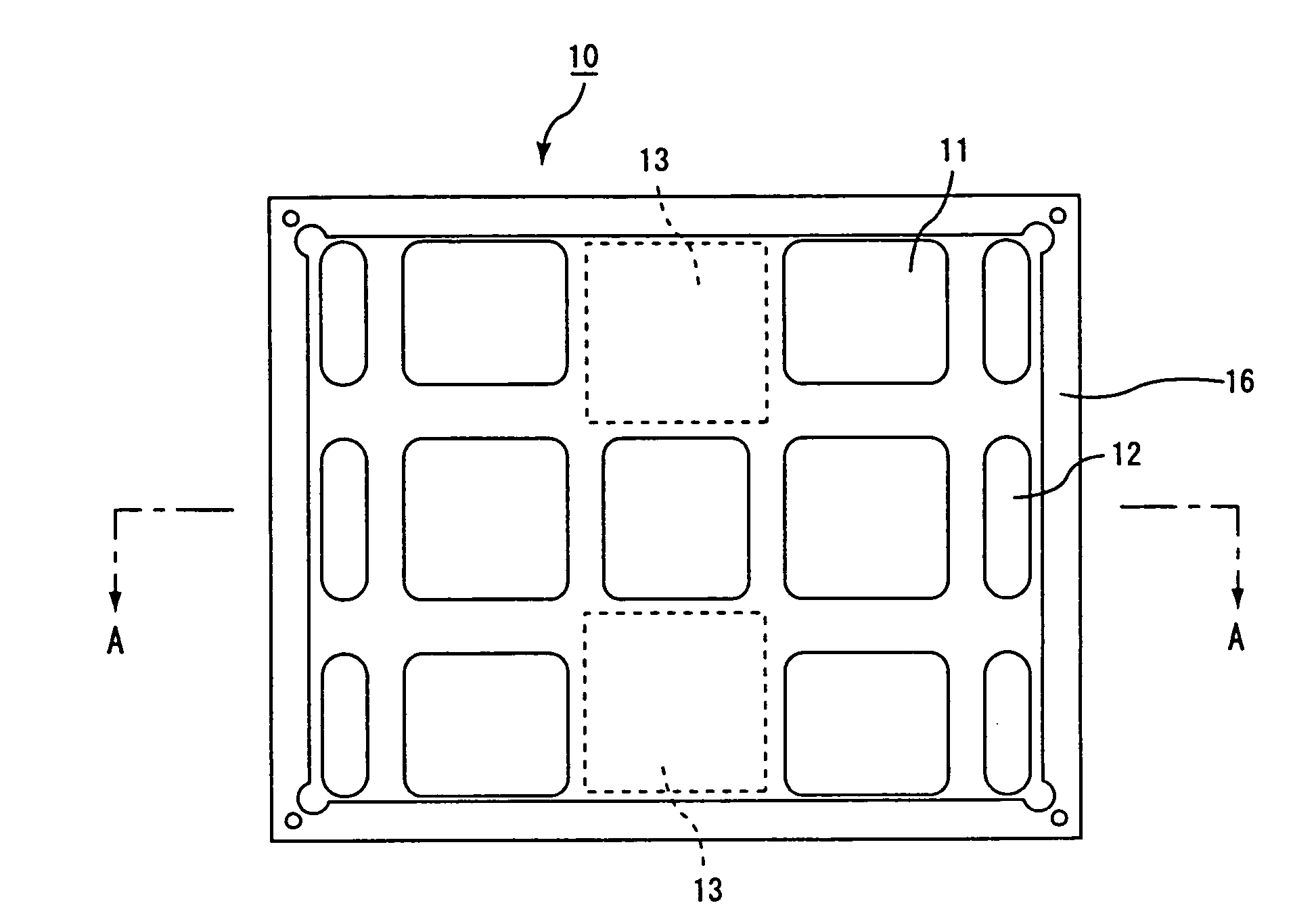
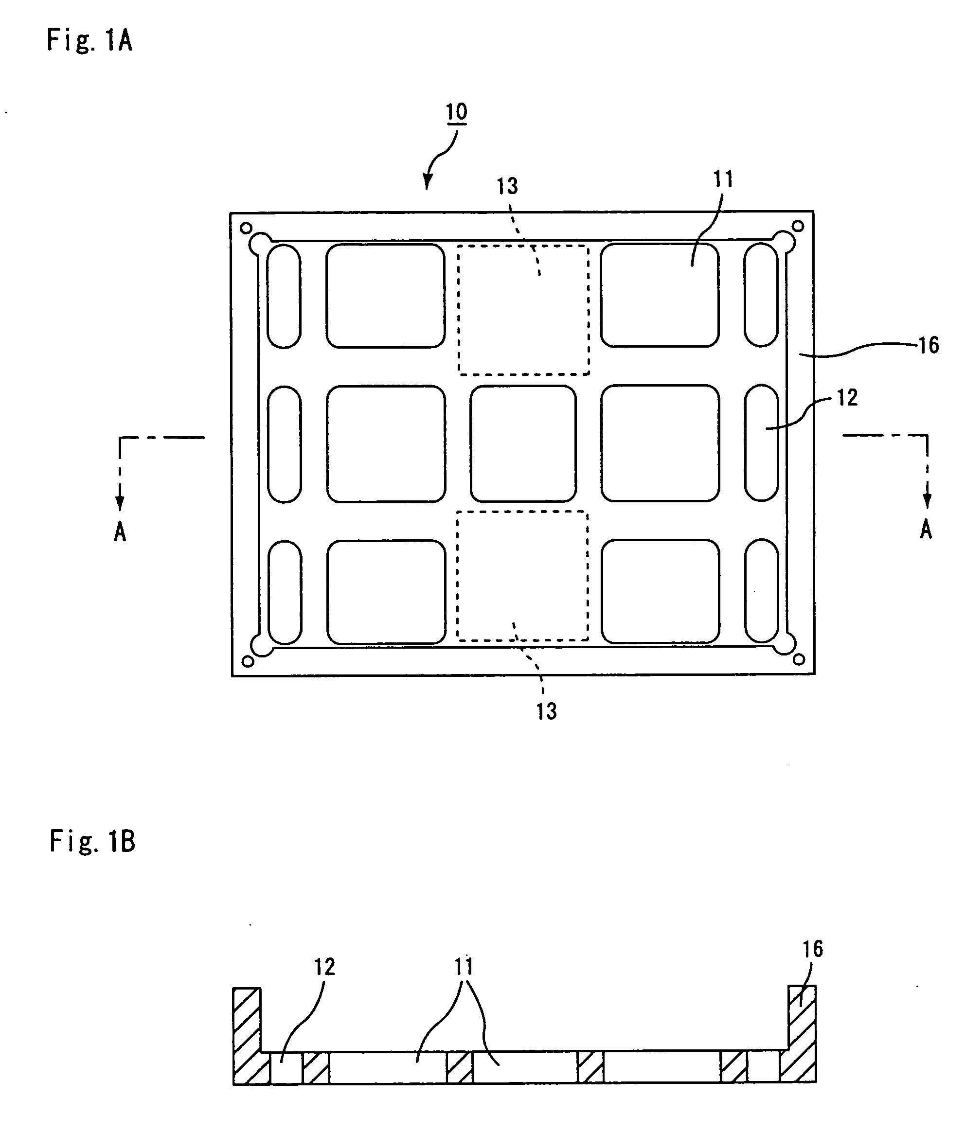
[0164] The same processes as Example 1 were carried out, except that the rate of the areas of portions on the bottom face of the jig for firing ceramics in which through holes were formed in the jig for firing ceramics to the area on the bottom face of the jig for firing ceramics was changed as shown in Table 1, so that ceramic filters were manufactured.

examples 8 to 14

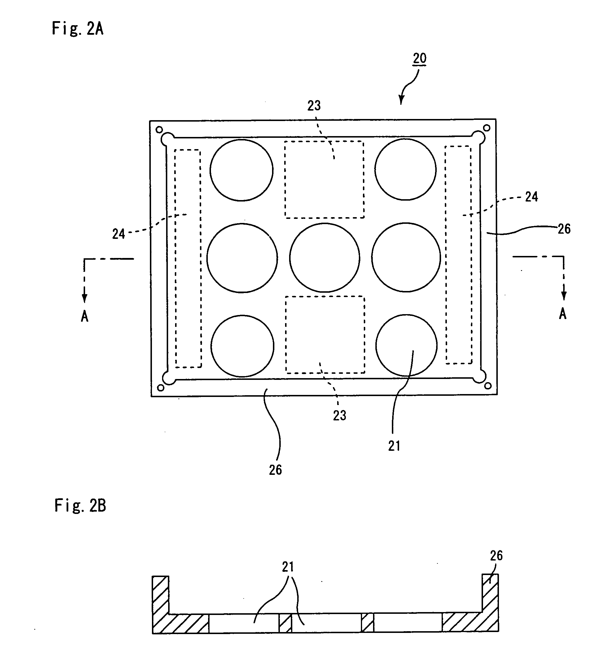
[0165] The same processes as Example 1 were carried out, except that the jig for firing ceramics was changed to the one shown in FIGS. 2A,B and that the rate of the areas of portions on the bottom face in which through holes were formed in the jig for firing ceramics to the area on the bottom face of the jig for firing ceramics was changed as shown in Table 1, so that ceramic filters were manufactured.


PUM

PropertyMeasurementUnit
temperatureaaaaaaaaaa
particle sizeaaaaaaaaaa

Abstract

A jig for firing ceramics, which is used by being piled up in multiple stages upon firing a ceramic formed body, of the present invention has a through hole and/or a cut-out portion formed in a portion thereof.

Description

CROSS-REFERENCE TO RELATED APPLICATIONS [0001] This application claims benefit of priority to Japanese Patent Application No. 2004-196047, filed on Jul. 1, 2004, International Patent Application PCT / JP2005 / 001423, filed on Feb. 1, 2005 as well as to International Patent Application PCT / JP2005 / 002076, filed on Feb. 10, 2005, the contents of which are incorporated by reference herein in their entirety.BACKGROUND OF THE INVENTION [0002] 1. Field of the Invention [0003] The present invention relates to: a jig for firing ceramics that is used for manufacturing a ceramic formed body; a manufacturing method for a porous ceramic body in which such a jig for firing ceramics is used; and a porous ceramic body manufactured by using the jig for firing ceramics. [0004] 2. Discussion of the Background [0005] In recent years, particulates contained in exhaust gases that are discharged from internal combustion engines of vehicles, such as a bus, a truck and the like, construction machines and the l...

Claims


Application Information

Patent Timeline
Patent Type & Authority Applications(United States)
IPC IPC(8): C04B35/64
CPCB28B11/243B28B11/248F27D5/00C04B2235/96C04B2235/80C04B2235/767C04B2235/6584C04B2235/6021C04B2235/5472C04B2235/5445C04B2235/5436C04B35/565C04B35/62655C04B35/6316C04B35/64C04B35/806C04B38/0645C04B2235/3418C04B2235/383C04B2235/5224C04B2235/526C04B35/185C04B35/195C04B35/48C04B38/0006C04B38/0054C04B38/0074C04B38/0605C04B38/0635C04B35/80F27D3/12
Inventor SAIJO, TAKAMITSUHIGUCHI, KOJI
Owner IBIDEN CO LTD
Why Eureka
Try Eureka