Fluid-filled vibration damping device

a technology of vibration damping and flue-filled filling, which is applied in the direction of shock absorbers, machine supports, mechanical equipment, etc., can solve the problems of narrow frequency range in which damping effects could be obtained, difficulty in tuning vibration properties, and sometimes needed damping effects of damping devices, etc., to achieve greater spring ratio, greater degree of freedom, and greater rubber volum

Inactive Publication Date: 2006-03-02
SUMITOMO RIKO CO LTD
View PDF6 Cites 23 Cited by
  • Summary
  • Abstract
  • Description
  • Claims
  • Application Information

AI Technical Summary

Benefits of technology

[0025] As will be apparent from the preceding description, in the fluid-filled type dynamic vibration damping device constructed according to the invention, a portion of the wall of one of the pair of operating fluid chambers located on both sides in the radial direction of the support shaft is made of the second flexible rubber layer separate from the rubber elastic body, so that a second equilibrium chamber is formed. This arrangement allows the radial damping properties obtained on the basis of the resonance action of the fluid flowing through the second orifice passage to be tuned with a greater degree of freedom by adjusting the configuration, properties, and the like of the second flexible rubber layer, while ensuring advantageous support spring rigidity with the rubber elastic body. Particularly in comparison to the fluid-filled vibration damping device relating to the prior application disclosed in JP-A-2002-327789, the damping effects based on the resonance action of the fluid which are brought about against radially input vibrations can be obtained over an even broader range of frequencies.
[0026] In the fluid-filled vibration damping device according to this mode, it is possible to ensure greater rubber volume in the rubber elastic body in directions perpendicular to the direction in which the second pressure receiving chamber and second equilibrium chamber are facing, thereby making it possible to establish a greater spring ratio in the radial direction in which the second pressure receiving chamber and second equilibrium chamber are facing, and the radial direction perpendicular thereto. It is thus possible to obtain damping effects based on the resonance action of the fluid flowing through the second orifice passage in the radial direction in which the second pressure receiving chamber and second equilibrium chamber are facing, while obtaining effective high dynamic spring properties based on the rubber elastic body in the radial direction perpendicular to the direction in which the second pressure receiving chamber and second equilibrium chamber are facing.

Problems solved by technology

Meanwhile, the damping effects of damping devices are sometimes needed for vibrations input from a plurality of directions.
However, in the fluid-filled vibration damping device structured in this manner, the damping effects produced on the basis of the resonance action of the fluid flowing through the second orifice passage are relatively “peaky” during vibration input in axis-perpendicular directions, and a resulting problem was the narrow frequency range in which damping effects could be obtained.
It was thus difficult to tune the vibration properties, and there was the risk that the intended damping performance could not be satisfactorily achieved as a result of changes in the properties of the damping device or the frequency of the input vibrations due to changes over time or the driving conditions or inherent conditions of the vehicle.
However, since the wall springs of the operating fluid chambers are made of the rubber elastic body, adjustments of the wall spring rigidity directly affect the spring properties of the rubber elastic body, namely, the support spring rigidity of the damping device, and the like.
Resulting problems are that, in actuality, it is extremely difficult to adjust the wall springs of the operating fluid chambers with a sufficient degree of freedom, and the degree of freedom with which the second orifice passage can be tuned is limited.
Although tuning can be addressed based on the length and cross section area of the second orifice passage, the second orifice passage is also limited in terms of formable space or structure, or in terms of ensuring fluid flow volume.
In the damping device described in JP-A-2002-327789, the need to form appreciable voids for the rubber elastic body unavoidably results in a dramatic loss of support spring rigidity in the damping device main unit.
It is thus not practical in fields requiring significant support spring rigidity.
Furthermore, considering the fact that automobile engine mounts are often required to have high dynamic spring rigidity in the lateral direction of the vehicle in order to address transversal gravity when the vehicle travels around corners, the structure described in JP-A-2002-327789 for forming appreciable voids in the rubber elastic body area acting as the compression spring in the lateral direction of the vehicle is unlikely to be considered a desirable structure, at least for automobile engine mounts.

Method used


Image

  • Fluid-filled vibration damping device
  • Fluid-filled vibration damping device
  • Fluid-filled vibration damping device

Examples


Embodiment Construction

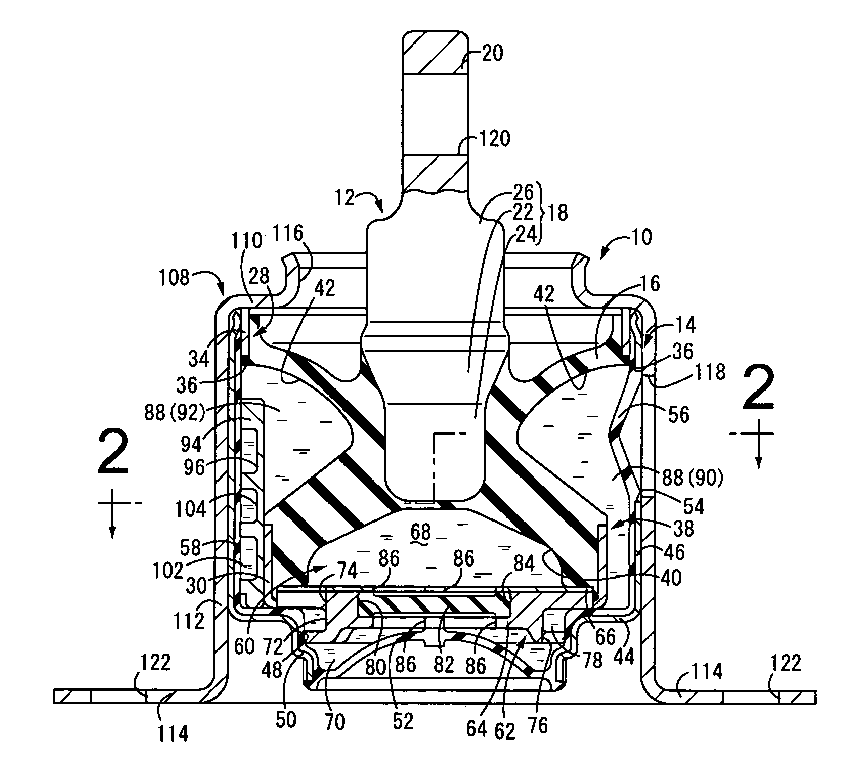
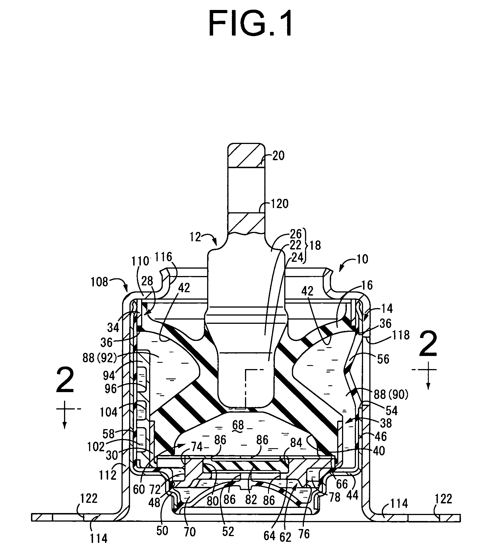
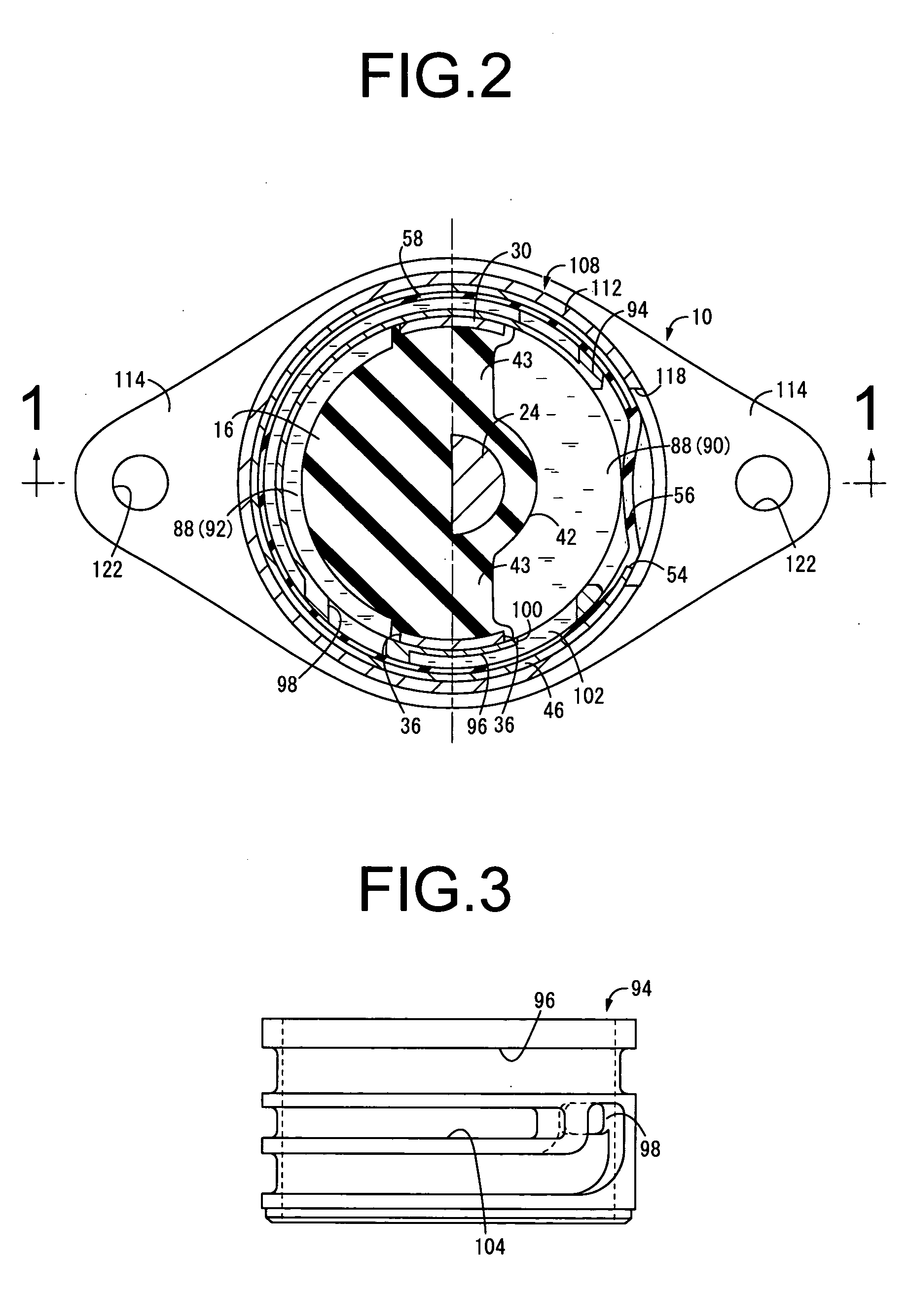
[0036]FIGS. 1 and 2 illustrate an automobile engine mount 10 in a first embodiment of the invention. This engine mount 10 has a construction wherein a metallic first mounting member 12 and a metallic second mounting member 14 are disposed apart, and a rubber elastic body 16 elastically connects the first mounting member 12 and second mounting member 14, with the first mounting member 12 attached to an automobile power unit and the second mounting member 14 attached to an automobile body by an attachment bracket 108, whereby the power unit is supported in a vibration-damped manner relative to the body. The engine mount 10 in this embodiment is mounted with the vertical direction in FIG. 1 being in a generally perpendicular vertical direction. As a rule, in the following description, the vertical direction refers to the vertical direction in FIG. 1.

[0037] More specifically, the first mounting member 12 comprises a support shaft 18 in the shape of a solid, round rod of small diameter,...


PUM


Abstract

A fluid-filled vibration damping device comprising: a rubber elastic body connecting the first and second mounting members; a first pressure receiving chamber partially formed by the elastic body; a first equilibrium chamber partially formed by a first flexible rubber layer; a first orifice passage connecting the first pressure receiving and equilibrium chambers. The elastic body has a pair of pockets open in its outer circumferential surface and located on both sides in a diametric direction of the support shaft of the first mounting member, while being fluid-tightly covered by the second mounting member to form a pair of operating fluid chambers which are connected by a second orifice passage. The operating fluid chambers functions as a second receiving pressure chamber partially formed by the rubber elastic body and a second equilibrium chamber partially formed by a second flexible rubber layer.

Description

INCORPORATED BY REFERENCE [0001] The disclosure of Japanese Patent Application No. 2004-245327 filed on Aug. 25, 2004 including the specification, drawings and abstract is incorporated herein by reference in its entirety. BACKGROUND OF THE INVENTION [0002] 1. Field of the Invention [0003] The present invention relates to a fluid-filled vibration damping device in which damping effects are obtained based on the flow action of a non-compressible fluid sealed in the interior thereof. More particularly, the invention is concerned with such a fluid-filled vibration damping device in which effective damping effects are brought about based on the flow action of a non-compressible fluid against input in both of two directions, i.e., the center axial direction and a direction perpendicular to the axis, making the device suitable for use as automobile engine mounts, for example. [0004] 2. Description of the Related Art [0005] A fluid-filled vibration damping device having a non-compressible f...

Claims


Application Information

Patent Timeline
Patent Type & Authority Applications(United States)
IPC IPC(8): F16F13/00
CPCF16F13/10F16F13/108F16F13/105
Inventor TANAKA, EIJIYANO, KATSUHISA
Owner SUMITOMO RIKO CO LTD
Why Eureka
Try Eureka