Phased array antenna with steerable null

a phased array antenna and null technology, applied in the direction of antennas, electrical appliances, individually energized antenna arrays, etc., to achieve the effect of reducing the energy in the null beam azimuth

Inactive Publication Date: 2006-03-02
PARATEK MICROWAVE INC
View PDF37 Cites 15 Cited by
  • Summary
  • Abstract
  • Description
  • Claims
  • Application Information

AI Technical Summary

Benefits of technology

[0005] Yet another embodiment of the present invention provides a method of creating a steerable null in a phased array antenna, comprising disposing an array of patch antennas within a receiver, combining the patch antennas by a switch / phase shifter network into a selected sequential group and stepping the group through the patch antennas thereby creating a plurality of main beam positions with at least one of the main beam positions capable of being active with the remaining main beam positions idle, and sampling energy from the remaining idle antenna elements in order to form a second beam that is capable of creating a null signal in the direction of the second beam. In an embodiment of the present invention, the null may be generated on the strongest undesirable emitter by: setting the main beam azimuth, setting the null beam azimuth, measuring the RSSI, and manipulating the switch / phase shifter to minimize energy in the null beam azimuth.

Problems solved by technology

One important difficulty with wireless communication can be interference, which creates a requirement for communication directional control and interference mitigation.

Method used


Image

  • Phased array antenna with steerable null
  • Phased array antenna with steerable null
  • Phased array antenna with steerable null

Examples


Embodiment Construction

[0009] In the following detailed description, numerous specific details are set forth in order to provide a thorough understanding of the invention. However, it will be understood by those skilled in the art that the present invention may be practiced without these specific details. In other instances, well-known methods, procedures, components and circuits have not been described in detail so as not to obscure the present invention.

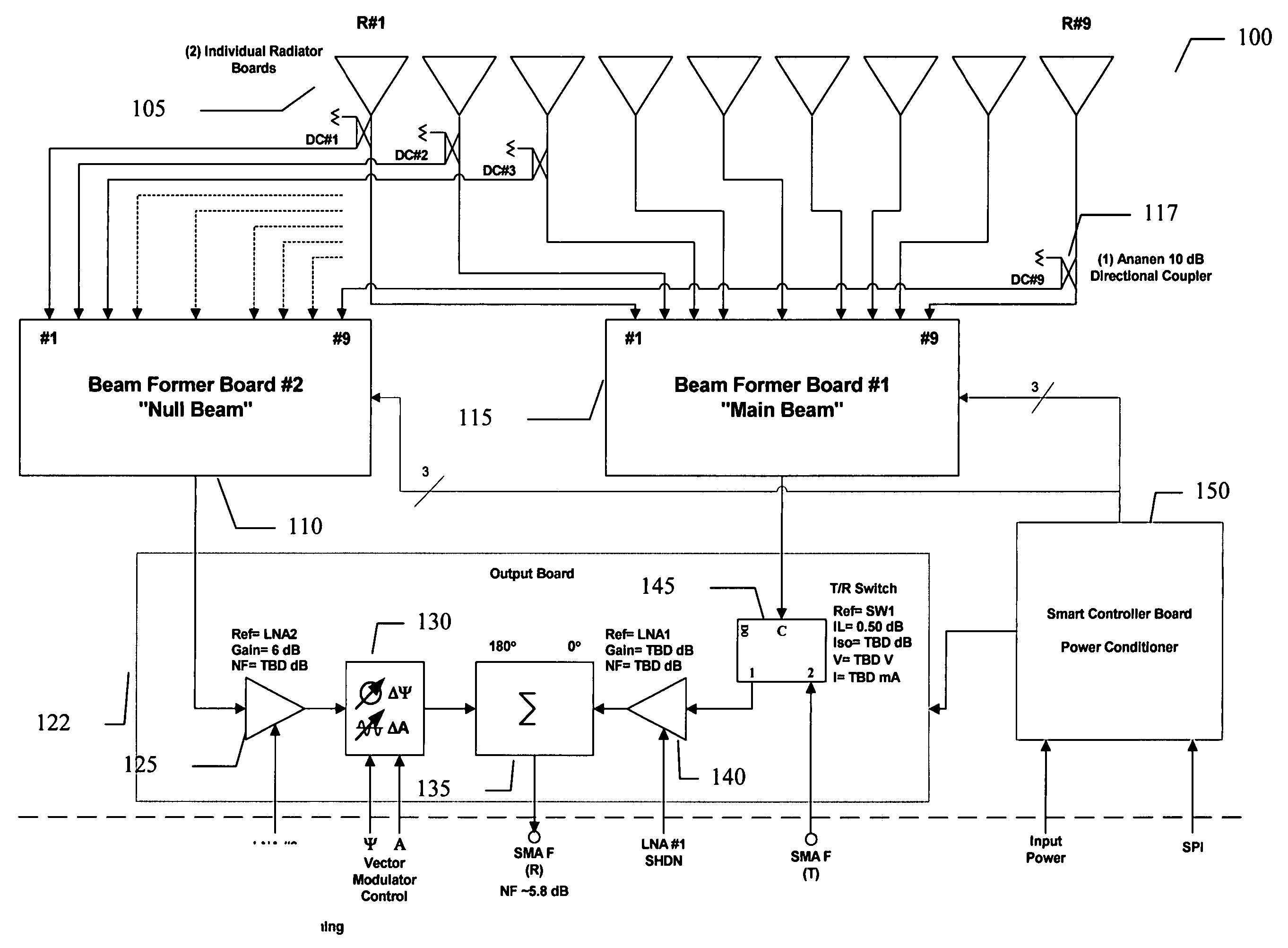
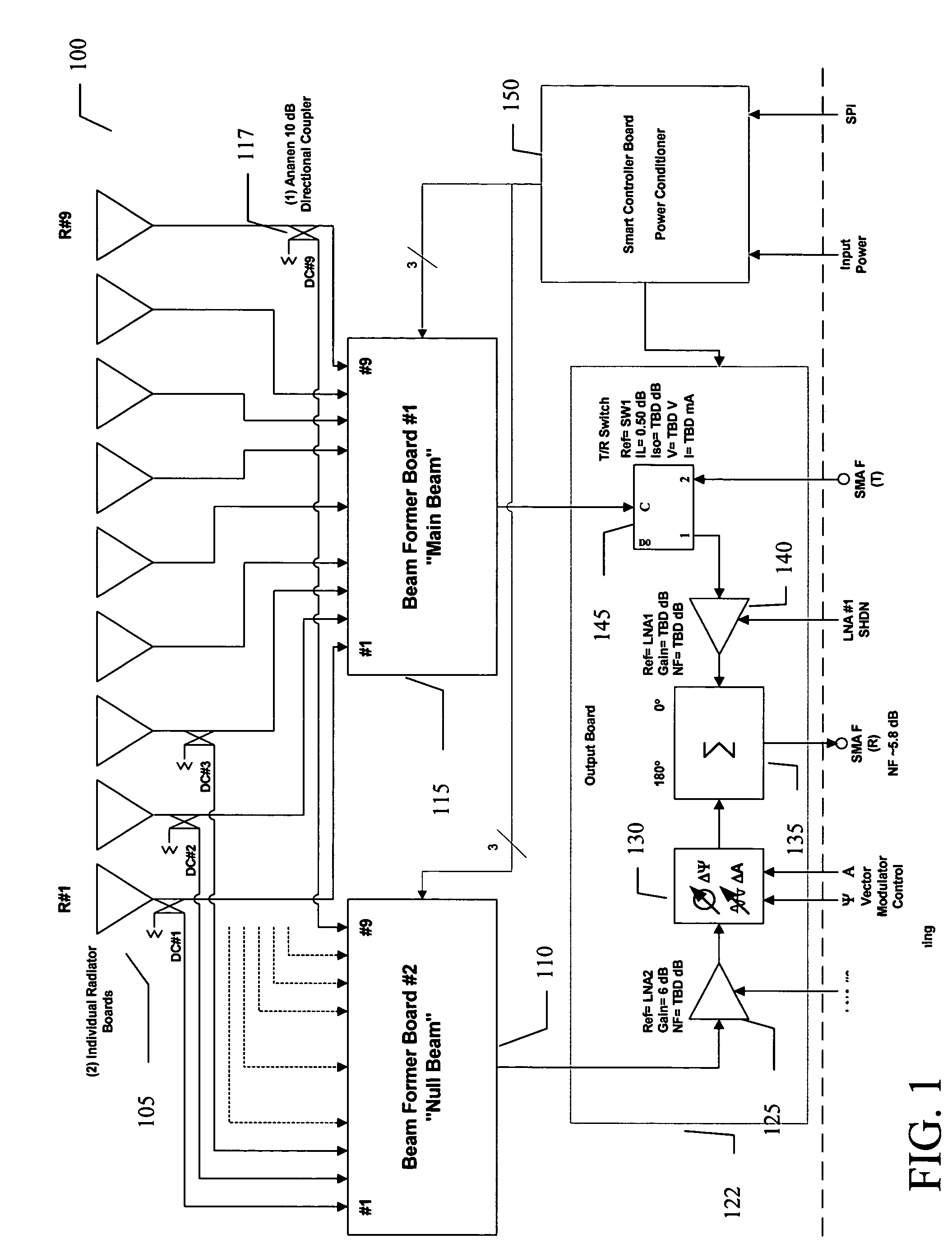
[0010] An embodiment of the present invention provides at FIG. 1 a“steerable null” for a 360 degrees phased array antenna (PAA) 100, although the present invention is not limited to specific radius of performance. The PAA 100 may use a circularly disposed array of nine microstrip patch antennas 105, having vertical polarization and dual outputs. The dual output may be implemented by use of directional couplers, DC 1-9 illustrated generally as 117, to sample energy from the element without taking too large a quantity from a main beam 115.

[0011] A specia...


PUM


Abstract

An embodiment of the present invention provides an apparatus, comprising an array of patch antennas and a switch/phase shifter network capable of combining the patch antennas in a selected sequential group and wherein by stepping the group throughout the patch antennas, a plurality of main beam positions can be created with at least one of the main beam positions capable of being active with the remaining main beam positions idle, and wherein by sampling energy from the remaining idle antenna elements, a second beam is formed that is capable of creating a null signal in the direction of the second beam. In an embodiment of the present invention, the array of patch antennas may be a circular array and the stepping the group around the array is stepping the group around a circumference of the circular array of patch antennas.

Description

CROSS REFERENCE TO RELATED PATENT APPLICATION [0001] This application claims the benefit of U.S. Provisional Patent Application No. 60 / 601,430, filed Aug. 14, 2004, entitled, “PHASED ARRAY ANTENNA WITH STEERABLE NULL”.BACKGROUND OF THE INVENTION [0002] Wireless communication has become pervasive and important throughout society. There are constant needs for improvement in wireless devices that facilitate such communication. One important difficulty with wireless communication can be interference, which creates a requirement for communication directional control and interference mitigation. Thus, a strong need exists for wireless devices and communication methods that may use phased array antennas with steerable nulls. SUMMARY OF THE INVENTION [0003] An embodiment of the present invention provides an apparatus, comprising an array of patch antennas and a switch / phase shifter network capable of combining the patch antennas in a selected sequential group and wherein by stepping the gro...

Claims


Application Information

Patent Timeline
Patent Type & Authority Applications(United States)
IPC IPC(8): H01Q21/08
CPCH01Q25/00H01Q3/2611
Inventor KRUTH, JEFFREY
Owner PARATEK MICROWAVE INC
Why Eureka
Try Eureka