Booster

Active Publication Date: 2006-03-02
JTEKT CORP
View PDF20 Cites 8 Cited by
  • Summary
  • Abstract
  • Description
  • Claims
  • Application Information

AI Technical Summary

Benefits of technology

[0008] Accordingly, it is an objective of the present invention to provide a booster that effectively prevents overshooting

Problems solved by technology

Thus, the deviation of the output voltage from the target voltage is significantly large.
As a result, the output voltage rises abruptly, which can

Method used


Image

  • Booster
  • Booster
  • Booster

Examples


first embodiment

[0037] Hereafter, an electric power steering (EPS) apparatus 1 having a booster 23 according to the present invention will be described with reference to the drawings.

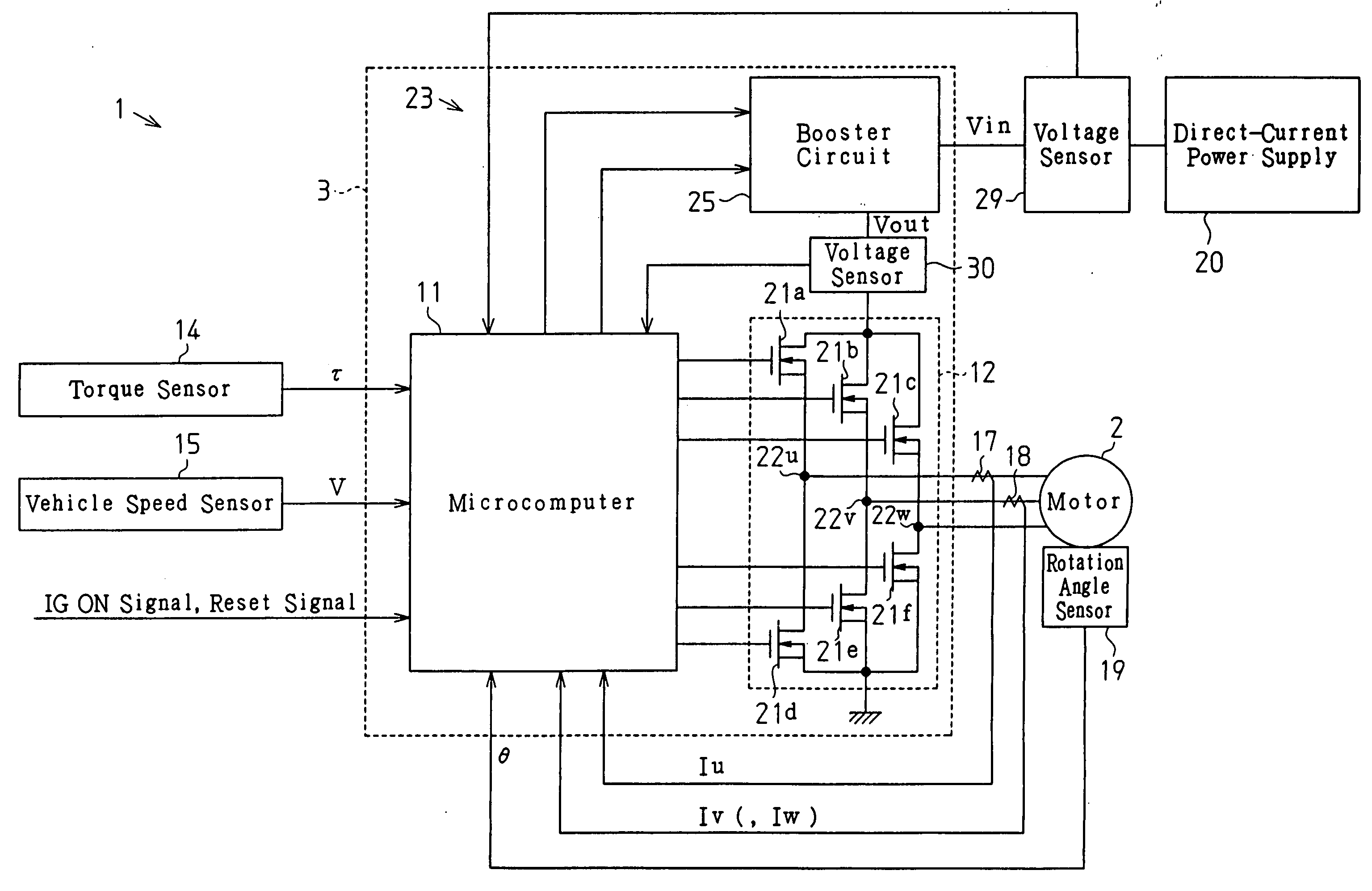
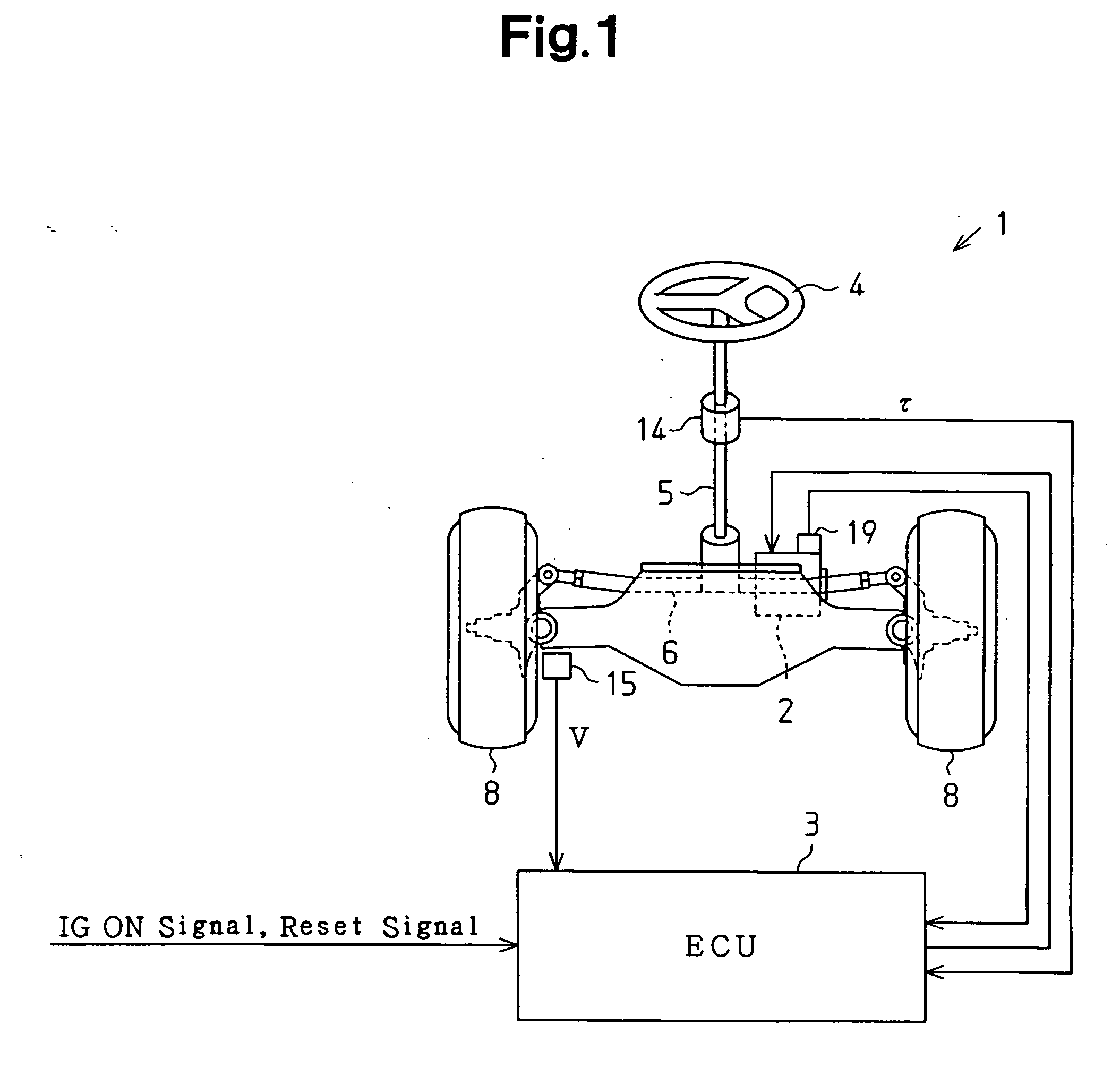
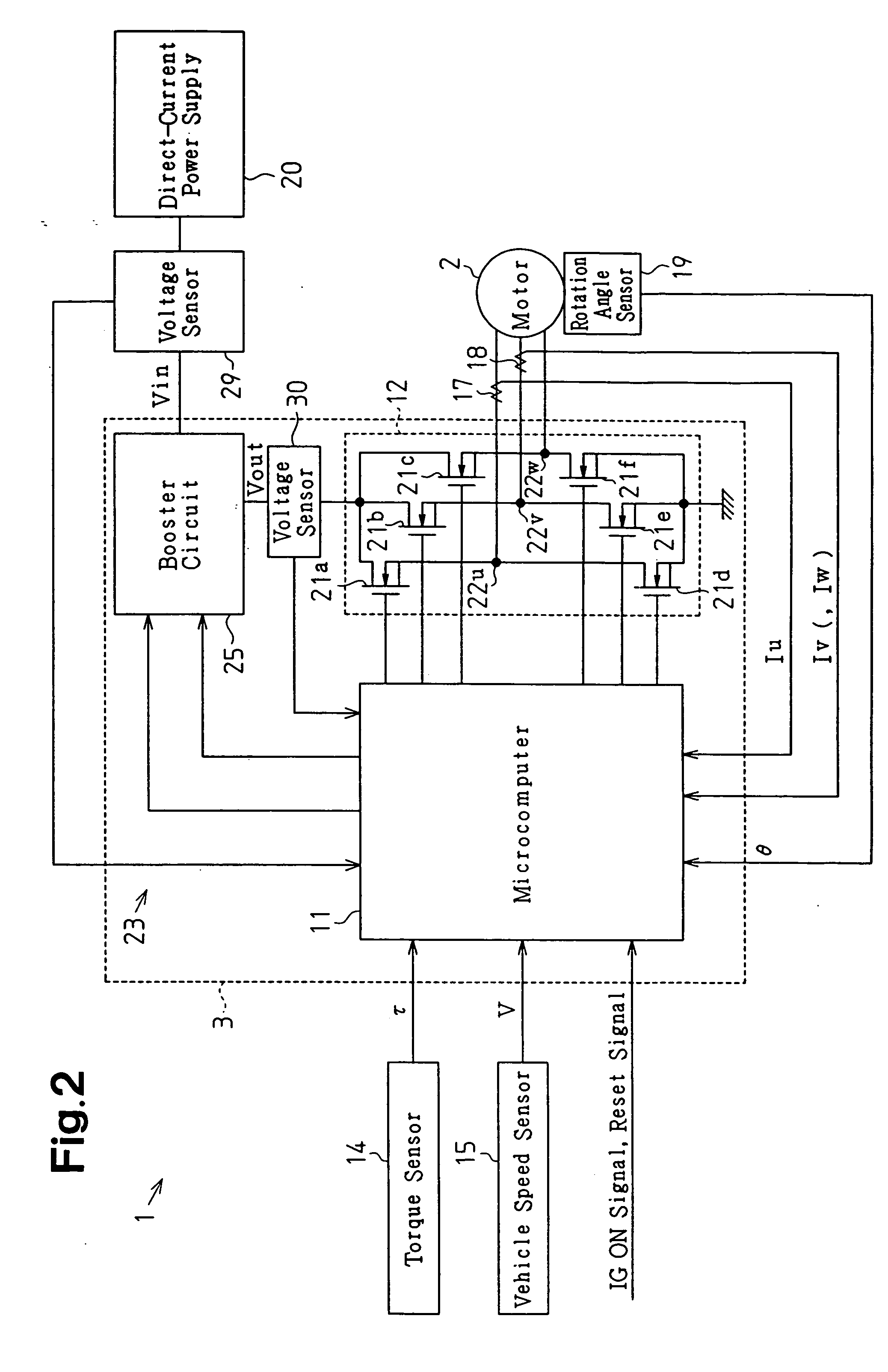
[0038] As shown in FIG. 1, the apparatus 1 includes a motor 2, which functions as a driving source for applying assisting force to the steering system of a vehicle, and an ECU 3 for controlling the motor 2.

[0039] A steering wheel 4 is coupled to a rack 6 with a steering shaft 5. Rotation of the steering shaft 5 caused by steering operation is converted into linear reciprocation of the rack 6 by means of a rack-and-pinion mechanism (not shown) and is transmitted to steered wheels 8. The EPS apparatus 1 of this embodiment is a rack type EPS apparatus, in which the motor 2 is arranged coaxial with the rack 6. Assisting torque generated by the motor 2 is transmitted to the rack 6 through a ball screw mechanism (not shown). The ECU 3 controls assisting force applied to the steering system by controlling the assisting torqu...

second embodiment

[0108] in the predetermined period T that corresponds to the period of the initial state, the duty ratio guarding coefficient Gd monotonously (proportionally) increases from 0 to 1.0 on the duty ratio guarding coefficient map 42a as the elapsed time t increases. At the initial state, the upper limit value Dlim is determined by multiplying the duty ratio guarding coefficient Gd, which is determined by using the duty ratio guarding coefficient map 42a, by the maximum value Dmax of the duty ratio instruction value (Dlim=Dmax×Gd). However, the upper limit value Dlim may be determined using a map that defines the relationship between the elapsed time t and the upper limit value Dlim.

[0109] The third embodiment may be modified as shown in FIG. 16. A microcomputer 61 according to the modified embodiment of FIG. 16 includes the initial state determination section 35 as in the first and second embodiments. The microcomputer 61 changes the feedback gain only at the initial state.

[0110] In t...

third embodiment

[0116] In the third embodiment and the modified embodiment of FIG. 17, the proportionality gain Kp0 and the integration gain Ki0, which have relatively large values of high responsivity, and the proportionality gain Kp1 and the integration gain Ki1, which have relatively small values of lower responsivity than that of the proportionality gain Kp0 and the integration gain Ki0, are switched based on the deviation of the output voltage Vout from the target voltage Vout* (or elapsed time from the start of the initial state). Instead, the proportionality gain and the integration gain may be switched among three or more stages.

[0117] A proportionality gain map 71a shown in FIG. 18(a) and an integration gain map 71b shown in FIG. 18(b), in which the proportionality gain Kp and the integration gain Ki are related to the deviation of the output voltage Vout from the target voltage Vout* may be used. In this case, the proportionality gain Kp and the integration gain Ki increase as the deviati...


PUM


Abstract

A booster includes a booster circuit and a microcomputer. The booster circuit outputs an output voltage. The output voltage is obtained by boosting a power supply voltage. The microcomputer controls the output voltage through a feedback control based on the deviation of the output voltage from a target voltage. The microcomputer determines whether the booster is in an initial state based on a start signal or a restart signal. When determining that the booster is in the initial state, the microcomputer corrects the target voltage such that the target voltage gradually increases from the power supply voltage as time elapses until a predetermined period elapses from the start of the initial state.

Description

CROSS-REFERENCE TO RELATED APPLICATIONS [0001] This application is based upon and claims the benefit of priority from prior Japanese Patent Application No. 2004-247154, filed on Aug. 26, 2004, the entire contents of which are incorporated herein by reference. BACKGROUND OF THE INVENTION [0002] The present invention relates to a booster that outputs an output voltage obtained by boosting a power supply voltage. [0003] In recent years, electric power steering (EPS) apparatuses, which use a motor as a driving source, are widely used as vehicle power steering apparatuses. Some of EPS apparatuses include a booster circuit to boost a supply source voltage. Such an EPS apparatus controls a motor based on a boosted voltage. [0004] For example, Japanese Laid-Open Patent Publication No. 2003-319700 discloses an EPS apparatus that includes a booster circuit provided between a vehicle power supply and a drive circuit, and a controller for controlling the booster circuit. The voltage boosted by ...

Claims


Application Information

Patent Timeline
IPC IPC(8): H02M3/18B62D5/04B62D6/00B62D101/00B62D119/00B62D137/00
CPCB62D5/046H02M2001/0025H02M3/157H02M1/36H02M1/0025
Inventor SUZUKI, HIROSHI
Owner JTEKT CORP
Why Eureka
Try Eureka