Image forming apparatus

a technology of image forming apparatus and forming device, which is applied in the direction of electrographic process apparatus, instruments, optics, etc., can solve the problems of developer on the surface of the sheet smearing the fixing device, the user's hand becoming soiled, and the surrounding area of the sheet being spattered and smeared

Inactive Publication Date: 2006-03-02
SHARP KK
View PDF2 Cites 4 Cited by
  • Summary
  • Abstract
  • Description
  • Claims
  • Application Information

AI Technical Summary

Benefits of technology

[0008] The present invention has been devised in consideration of these issues, and it is an object thereof to provide an image forming apparatus in which, even if an abnormality such as a jam occurs and the conveying of a sheet is stopped, the developer on the surface of the sheet does not spatter and smear surrounding areas and neither the user's hand nor the fixing device becomes soiled.
[0010] With this configuration, the outer side of the bent sheet can be held by hand when removing the sheet from the image forming apparatus so that the hand of the user does not become soiled. The sheet can then be folded in two by hand while the front surface of the sheet is facing inward, thereby enabling the prevention of spattering of the developer on the surface of the sheet.
[0012] With this configuration, the developer on the surface of the sheet does not smear the first convey path when an abnormality occurs. Furthermore, by setting the first convey path to pass through the fixing device and the second convey path to bypass the fixing device, the sheet will bypass the fixing device by switching from the first convey path to the second convey path when an abnormality such as a jam occurs, and therefore the developer on the surface of the sheet does not soil the fixing device.
[0019] With this configuration the charge is discharged at a grounding point at an area of the endless belt such that the electrostatic adhesion applied to the sheet at that area is weakened and the sheet can be made to separate easily from the endless belt. Moreover, the area on the endless belt is made ungrounded by the switching means when the sheet is conveyed on the second convey path. Thus, the power of the electrostatic adhesion on the sheet continues to be maintained at this area and the sheet can be conveyed reliably along the second convey path by the endless belt.

Problems solved by technology

In this regard, sometimes an abnormality such as a jam may occur to a sheet on which an image of a developer has been transferred such that the conveying of the sheet is stopped prior to the sheet being conveyed to the fixing device.
In this case, when the sheet is removed from the image forming apparatus, the image of the developer on the surface of the sheet is not fixed, and therefore problems have occurred such as the developer on the surface of the sheet spattering and smearing the surrounding area, or the user's hand becoming soiled.
In this case, a problem is caused in that the developer on the surface of the sheet smears the fixing device.
When the conveying of the sheet is stopped in a state in which a portion of the sheet is inserted into the fixing device and the sheet is sandwiched between the heating roller and the pressure roller, the developer on the surface of the sheet sometimes becomes thermally fused such that the developer adheres to the heating roller or the pressure roller, leading to smearing and abrasions on the surface of the rollers, and the rollers may become damaged.

Method used


Image

  • Image forming apparatus
  • Image forming apparatus
  • Image forming apparatus

Examples


Embodiment Construction

[0025] Hereinafter, embodiments of the present invention will be described in detail with reference to the accompanying drawings.

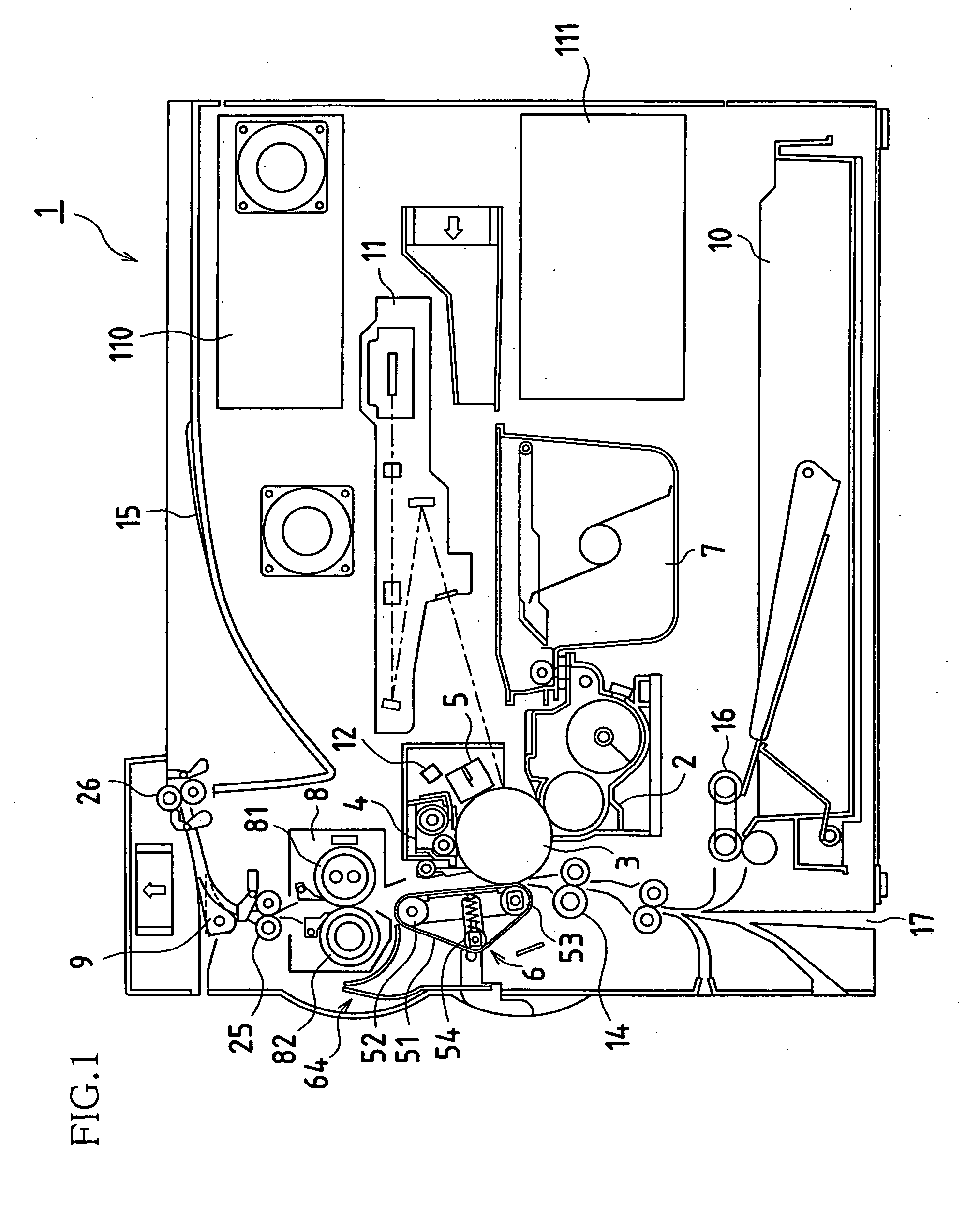
[0026]FIG. 1 is a lateral view showing an example of an image forming apparatus according to the present invention. The image forming apparatus 1 records and outputs images that have been read in by an image reading device (an unshown, integrated unit) or, as images, data received from a device (an image processing device such as a personal computer for example) that is externally connected to the image forming apparatus 1.

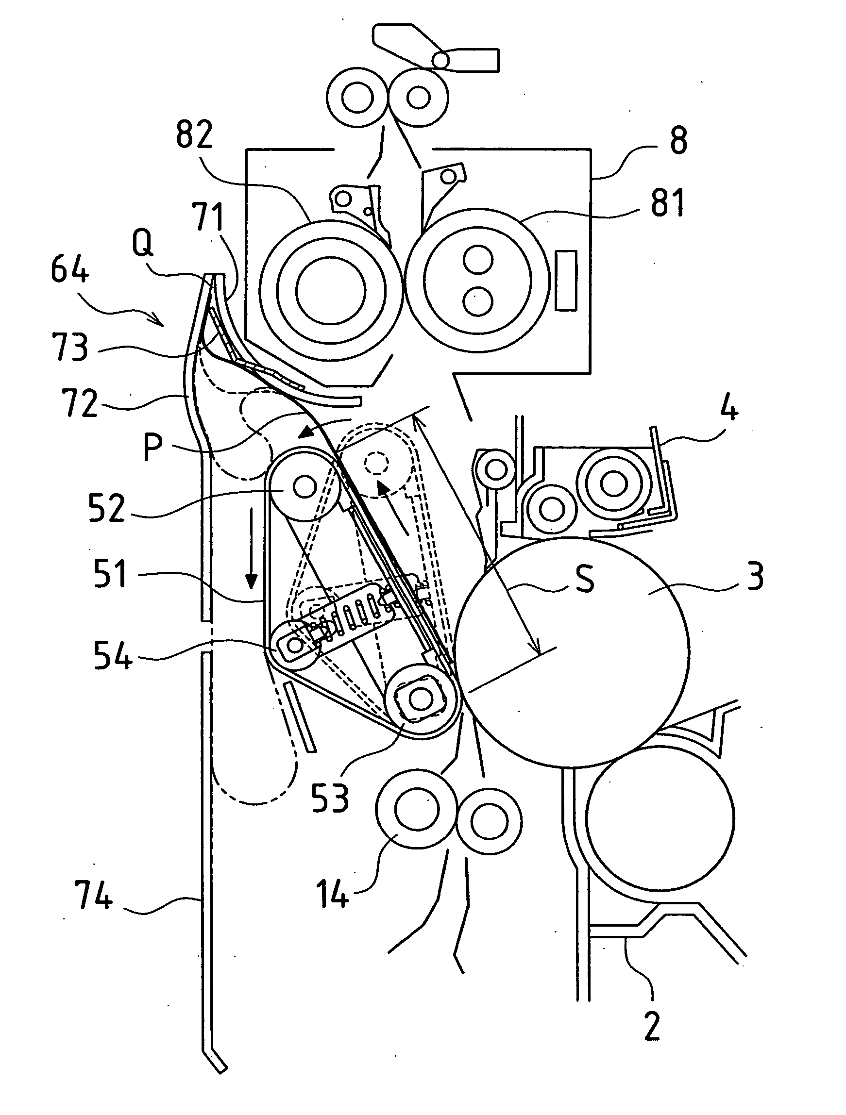
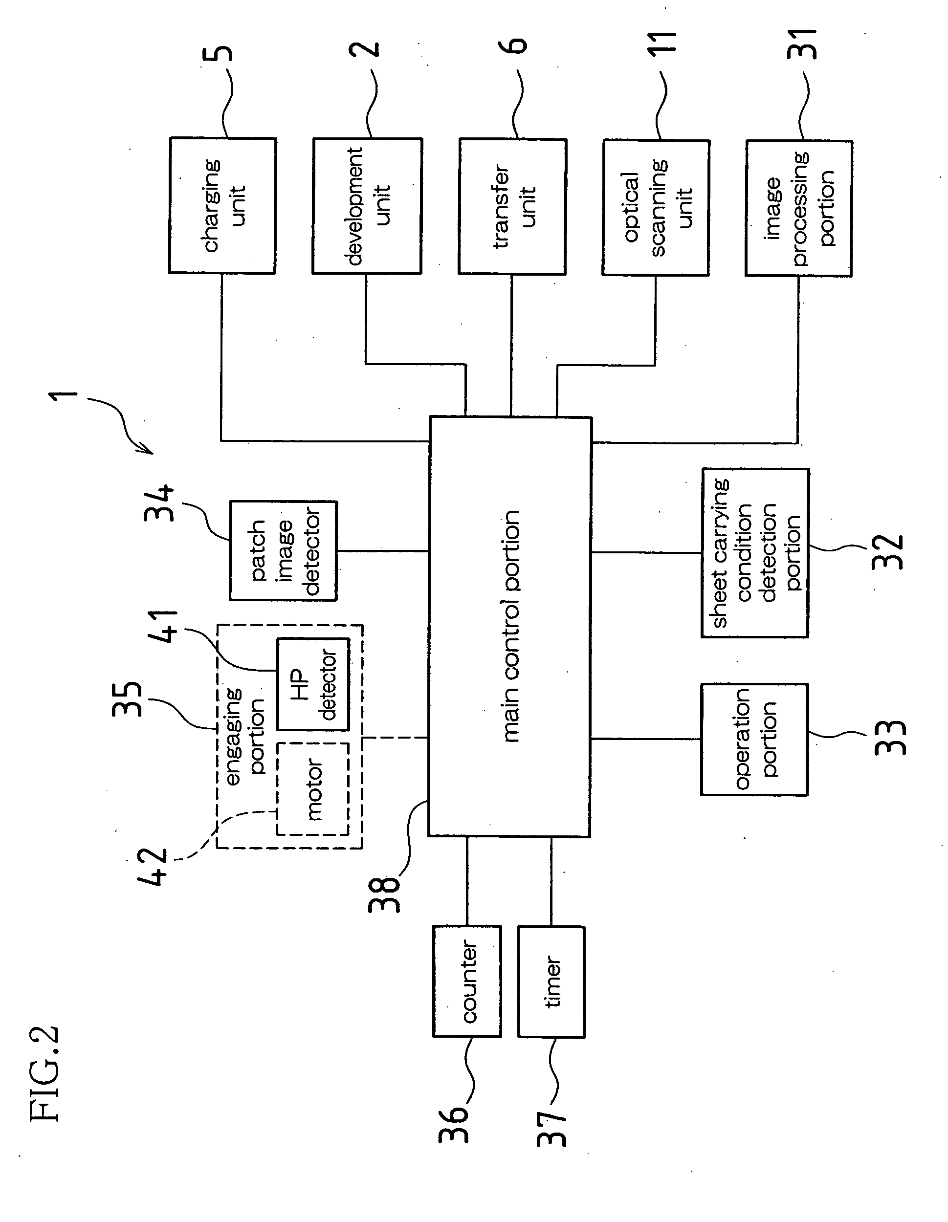
[0027] In the image forming apparatus 1, various processing units that convey out respective functions for image formation are arranged centered around a photosensitive drum 3, and an image-forming portion is constituted by these processing units. Namely, the image-forming portion is provided around the photosensitive drum 3 and is constituted by units including a charging unit 5, an optical scanning unit 11, a development unit 2, a tr...


PUM


Abstract

A sheet P on which an image of a developer is unfixed is recovered from a transfer unit 6 to a sheet recovery portion 64, the sheet P is bent with the surface of the sheet P on which the image of the developer has been transferred facing inward and, while remaining bent, the sheet P drops downward between an outer guide plate 72 and a transfer convey belt 51, then an openable cover 74 is opened to remove the sheet P.

Description

BACKGROUND OF THE INVENTION [0001] This application claims priority under 35 U.S.C. § 119(a) on Patent Application No. 2004-248772 filed in Japan on Aug. 27, 2004, the entire contents of which are hereby incorporated by reference. [0002] The present invention relates to electrophotographic image forming apparatuses such as copying machines, facsimile machines, and printers. [0003] In this type of image forming apparatus, an image is formed on a surface of a sheet while the sheet is being conveyed, and if an abnormality such as a jam occurs during the conveying of the sheet, the conveying of the sheet is stopped and an operation is conveyed out to solve the jam or other abnormality. Ordinarily, the conveying of the sheet is stopped at the same time as the abnormality occurs, or the conveying of the sheet is stopped after the sheet is conveyed to a location where the sheet can be removed from the image forming apparatus easily. [0004] For example, a technique is disclosed in JP 2003-3...

Claims


Application Information

Patent Timeline
Patent Type & Authority Applications(United States)
IPC IPC(8): G03G15/00
CPCG03G15/657G03G21/1638G03G2221/1675G03G2215/00552
Inventor TAKIGUCHI, TOSHIKI
Owner SHARP KK
Why Eureka
Try Eureka