Machining system with integrated chip hopper

a technology of chip hopper and machining system, which is applied in the direction of process control, machine control, instruments, etc., can solve the problems of expensive coolant filtration system, system not helping contain airborne particulates, oil mist, etc., to improve sealing and particulate containment, eliminate chip transferring equipment and associated costs, and reduce mess

Inactive Publication Date: 2006-03-02
FORD MOTOR CO
View PDF35 Cites 22 Cited by
  • Summary
  • Abstract
  • Description
  • Claims
  • Application Information

AI Technical Summary

Benefits of technology

[0017] One advantage of the present invention is improved sealing and particulate containment to reduce mess and eliminate chip conveyance equipment and the associated costs. Another advantage is that negative air pressure can be provided inside the machining system to help contain particulates and eliminate the need for a separate air handling or filtration system. Another advantage of the present invention is that airflow can be more readily controlled to prevent particulates from collecting on housing surfaces where they may interfere with machining operations.

Problems solved by technology

Consequently, these systems required expensive coolant filtration systems as well as coolant handling equipment to transport chips from the machine tool to the filtration system.
In addition, such systems did not help contain airborne particulates, such as oil mist.

Method used


Image

  • Machining system with integrated chip hopper
  • Machining system with integrated chip hopper
  • Machining system with integrated chip hopper

Examples


second embodiment

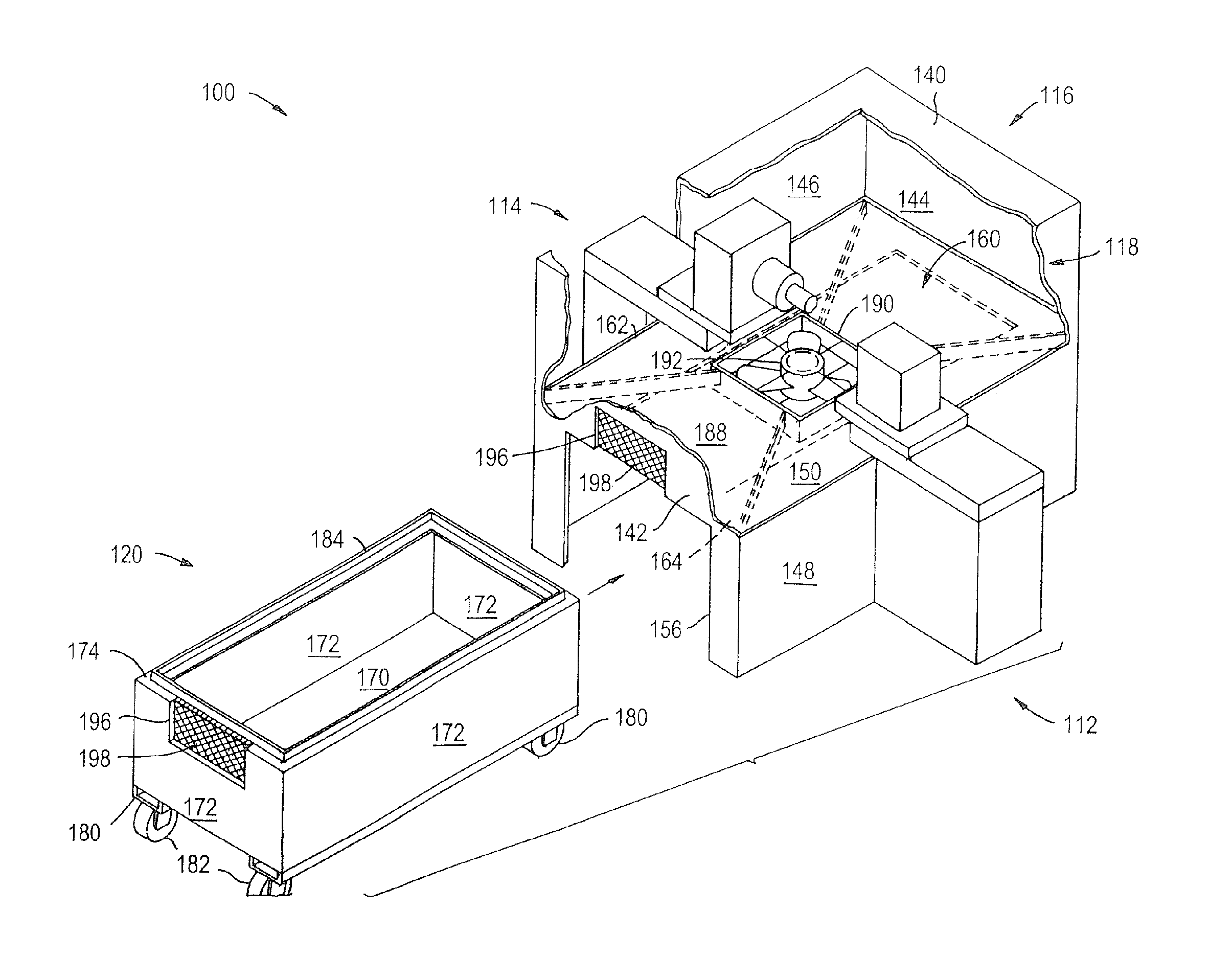
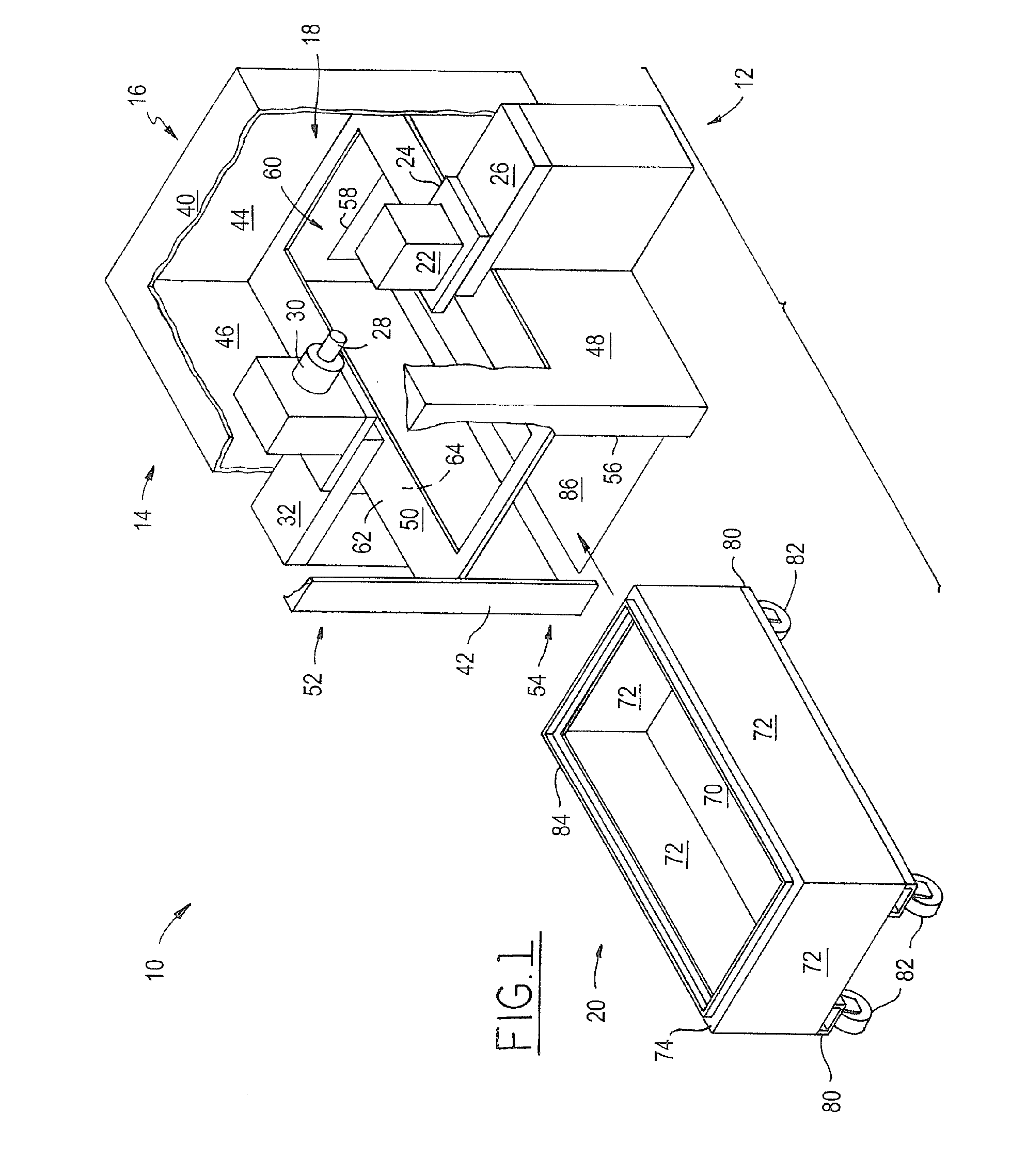
[0035] Referring to FIG. 2, the machining system 100 is shown. Similar to FIG. 1, the machining system 100 includes a workpiece presenter 112, a tool presenter 114, a housing 116, a machining envelope 118, and a hopper 120.

[0036] The housing includes a top panel 140, a front panel 142, a back panel 144, a left panel 146, a right panel 148, a mating portion 150, an upper portion 152, and a lower portion 154. The front panel 142 includes a first access port 156. The mating portion 150 defines an aperture 160 and includes a top surface 162 and a bottom surface 164.

[0037] The hopper 120 may include a bottom panel 170, a plurality of side panels 172, a top surface 174, one or more channels 180, one or more wheels 182, and a seal 184 as previously described.

[0038] A funnel 188 is disposed proximate one or more interior surfaces of the housing 116. The funnel 188 extends downward from the machining envelope 118 and includes an aperture 190 through which particulates are directed. The fun...

third embodiment

[0041] Referring to FIG. 3, the machining system 200 is shown. In this embodiment, machining system includes a workpiece presenter 202 and a tool presenter 204 as previously described. In addition, the machining system includes a moveable housing 206.

[0042] The moveable housing 206 includes a top panel 210, a bottom panel 212, a front panel 214, a back panel 216, a left panel 218, and a right panel 220. In addition, the housing 206 includes an upper portion 222 at least partially defining a machining envelope 224 and a lower portion 226 disposed proximate the upper portion 222.

[0043] The upper portion 222 may include first and second openings 230,232 to facilitate insertion and removal of at least a portion of the workpiece presenter 202 and tool presenter 204 as previously described. In addition, one or more flaps 234 may be disposed on the housing 206 and at least partially cover the opening 230,232 when the workpiece and / or cutting tool are removed from the machining envelope 22...

fourth embodiment

[0046] Referring to FIG. 4, the machining system 300 is shown. In this embodiment, machining system includes a workpiece presenter 302, a tool presenter 304, and a moveable housing 306 having an upper portion 322 that at least partially defines a machining envelope 324 and a lower portion 326 disposed proximate the upper portion 322 as previously described. In addition, the upper portion 322 includes a funnel 330 having an aperture 332 and optionally a blower 334 and one or more vent openings 336 that may include a filter 338 similar to the embodiment shown in FIG. 2.

[0047] Optionally, any of the embodiments of the present invention may incorporate internal or external blowers or air handling systems adapted to provide negative air pressure in the machining area.

[0048] The present invention may be used with any suitable machining system or process, such as dry machining or a minimum quantity lubrication (MQL) machining system in which low levels of lubricant are provided through th...


PUM

PropertyMeasurementUnit
forceaaaaaaaaaa
pressureaaaaaaaaaa
air pressureaaaaaaaaaa

Abstract

A machining system having a machining envelope, a housing, a hopper, and a seal. The housing defines at least a portion of the machining envelope. The hopper has a top surface defining an opening. The seal is disposed between the housing and the top surface. The hopper is configured to receive particulates when positioned below the machining envelope.

Description

BACKGROUND OF THE INVENTION [0001] 1. Field of the Invention [0002] The present invention relates to a machining system having a hopper adapted to receive particulates, such as chips. [0003] 2. Background Art [0004] Previously, machine tools used coolant to flush chips from workpiece and machine tool surfaces. Chips were removed from the coolant using a filtration system that deposited chips on an indexable media and dumped the deposited chips into a chip hopper. In such systems the filtration system and chip hopper were located apart from the machine tool. Consequently, these systems required expensive coolant filtration systems as well as coolant handling equipment to transport chips from the machine tool to the filtration system. In addition, such systems did not help contain airborne particulates, such as oil mist. As a result, air filtration equipment was needed to improve air quality. [0005] Before Applicants' invention, a system for containing particulates, such as oil mist a...

Claims


Application Information

Patent Timeline
Patent Type & Authority Applications(United States)
IPC IPC(8): B23C1/00B23Q11/02B23Q11/08B23Q11/00
CPCB23Q11/0042B23Q11/0067Y10S29/079Y10T409/304088Y10T408/50Y10T74/2191Y10T409/30392Y10S29/094Y10T83/2092B08B5/00B08B13/00B23Q11/006
Inventor ANDERSON, JAMESSTOLL, ALEXANDERLOCH, THOMAS
Owner FORD MOTOR CO
Why Eureka
Try Eureka