Device for removing metallic objects from a railway bed

a technology for railway beds and metallic objects, applied in transportation items, loading/unloading vehicles, ways, etc., can solve problems such as substantial wear, railway bed accumulation of metallic objects such as railroad spikes, and replacement of conveyor belts

Inactive Publication Date: 2006-03-02
SPERLING RAILWAY SERVICES
View PDF11 Cites 17 Cited by
  • Summary
  • Abstract
  • Description
  • Claims
  • Application Information

AI Technical Summary

Problems solved by technology

One result of this work is the accumulation of metallic objects such as railroad spikes along the railway bed.
Due to the large number of spikes and other metallic objects used, the railway bed which repair workers traverse daily may easily be littered with thousands of used spikes and other metallic objects which need to be removed.
One problem arising with the use of these cars is the replacement of the conveyor belts, which experience a substantial amount of wear.
The replacement of the conveyor belts has been a tedious and time-consuming task.
One solution involves the use of laced belts, which, however, present accelerated wear problems.
While the laced-belt solution facilitates removal and replacement, the accelerated wear problem noted above arises due to the joint between the elastomeric material and the metal teeth, which naturally creates a point of wear as the conveyor belt moves about its track.
The problem arising is that the continuous-loop belts must be moved laterally, that is, transverse to their length, in order to remove a worn belt from its track and install a new belt on the track.
This movement has been particularly difficult because the conveyor belt assembly and various other structure interferes with this lateral movement.
Another interfering factor is the structure about which the conveyor belt assembly pivots in order for the above-noted lift to raise one end of the conveyor belt assembly.
The prior art hydraulic lines are also situated external to the conveyor belt loop so that they too interfere with removal and installation of the belt unless the lines are disconnected.

Method used


Image

  • Device for removing metallic objects from a railway bed
  • Device for removing metallic objects from a railway bed
  • Device for removing metallic objects from a railway bed

Examples


Embodiment Construction

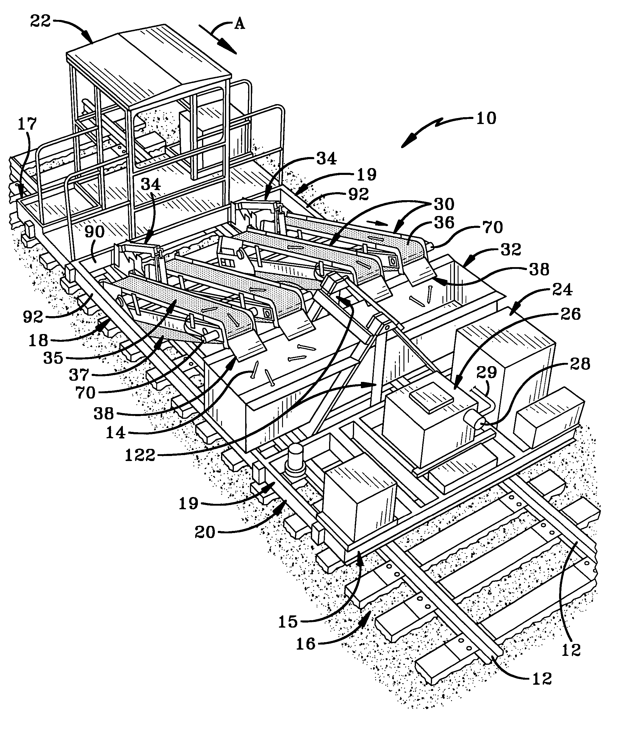
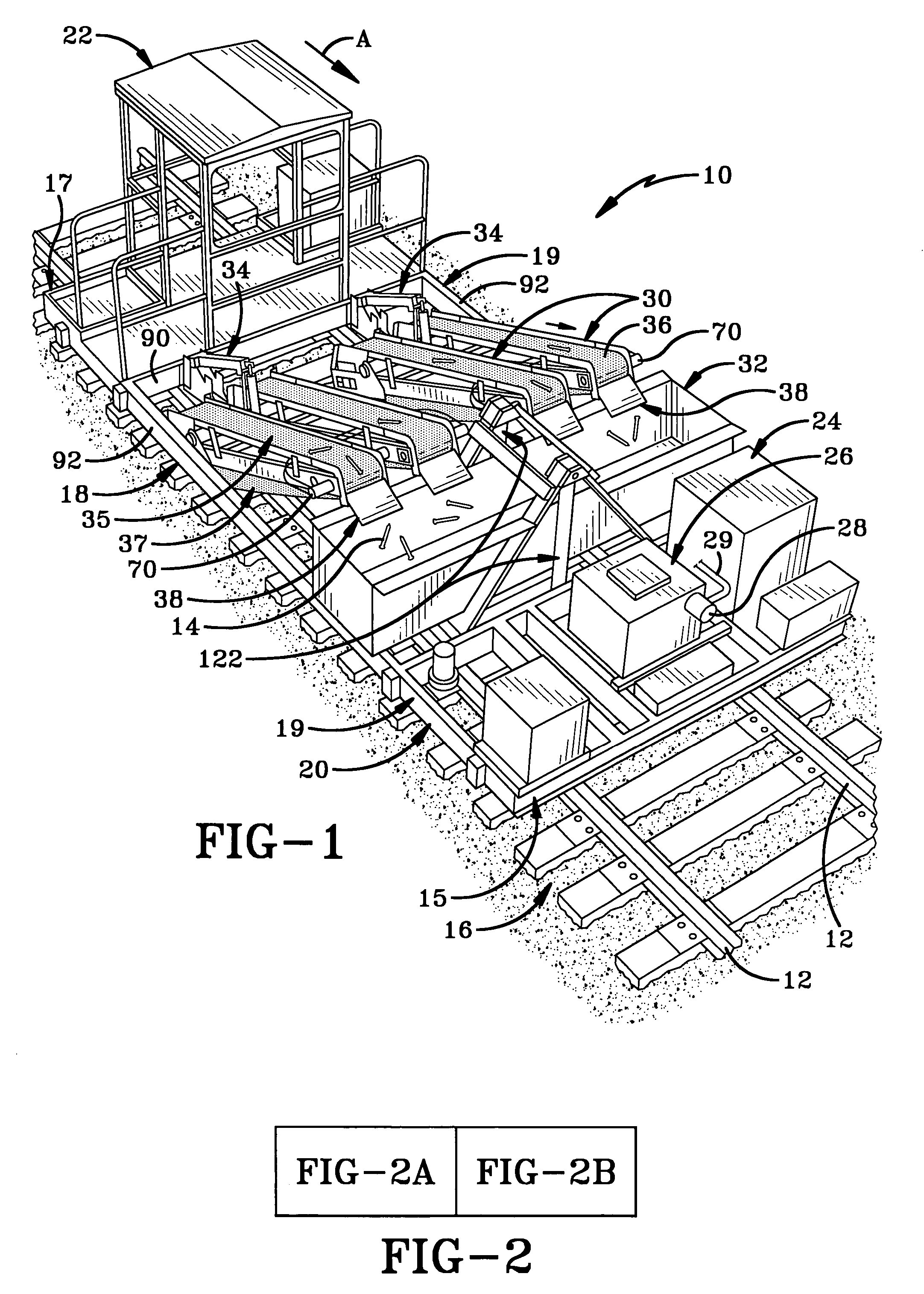
[0030] The retriever or the device of the present invention is shown generally at 10 in FIG. 1. Retriever 10 is configured to travel along a pair of spaced rails 12 of a railroad track in the direction of Arrow A in FIG. 1 and remove metallic objects such as railroad spikes 14 from a railway bed 16. Retriever 10 includes a car 18 having a frame 20. Car 18 has a front end 15, a rear end 17 and a pair of opposed sides 19 each extending from front end 15 to rear end 17. Frame 20 includes a pair of longitudinal side frame members or side rails 92 extending along respective sides 19 of car 18. A cabin 22 from which retriever 10 may be driven is mounted on frame 20. An engine 24 is mounted on frame 20 to power retriever 10 for travel on railroad rails 12. A hydraulic reservoir 26 and hydraulic pump 28 are also mounted on frame 20 to provide hydraulic power to various mechanisms on retriever 10 via hydraulic lines. Retriever 10 includes four conveyor belt assemblies 30 for picking up and t...


PUM


Abstract

A machine which travels on railroad rails includes a conveyor belt which transports metallic objects from a railway bed into a hopper. The conveyor belt revolves around a pair of rollers mounted on the framework of a conveyor belt assembly. One roller magnetically picks up the metallic objects and a hydraulic motor powers the other roller to drive the conveyor belt. The magnetized roller is mounted via two mounting bearings which slidably engage the assembly. An adjustment bolt on the assembly engages the mounting bearing to move the magnetized roller to adjust conveyor belt tension to facilitate replacement of the belt. A lift beside the assembly raises and lowers one end of the assembly which rotates about a pivot tube within the conveyor belt. The lift, pivot tube and hydraulic lines connected to the motor are all situated to allow the belt to be removed without interference therefrom.

Description

BACKGROUND OF THE INVENTION [0001] 1. Technical Field [0002] The present invention relates to a device which travels on railroad track rails and removes metallic objects, such as railroad spikes, from a railway bed. More particularly, the invention relates to such a device which has a conveyor belt for transporting the metallic objects from adjacent the railway bed into containers. Specifically, the invention relates to such a device which is configured to facilitate removal of worn conveyor belts and installation of new conveyor belts. [0003] 2. Background Information [0004] In the railway industry, railroad track is constantly being repaired or replaced. One result of this work is the accumulation of metallic objects such as railroad spikes along the railway bed. Due to the large number of spikes and other metallic objects used, the railway bed which repair workers traverse daily may easily be littered with thousands of used spikes and other metallic objects which need to be remov...

Claims


Application Information

Patent Timeline
Patent Type & Authority Applications(United States)
IPC IPC(8): B60P1/00
CPCB61D15/00E01B29/26E01H8/00E01H1/14B03C1/16B03C1/22B03C1/30
Inventor SPERLING, FRED S.
Owner SPERLING RAILWAY SERVICES
Why Eureka
Try Eureka