Preform structure and method of manufacturing preform and bearing housing structure having the preform formed into metal matrix composite of cylinder block

a technology of bearing housing and preform, which is applied in the direction of metal extrusion, manufacturing tools, transportation and packaging, etc., can solve the problems of increased noise or vibration of engines, high defect rate, and preform subject to oxidization, so as to achieve the desired linear expansion and strength coefficient, easy infiltration of base materials, and adequate interfacial strength

Inactive Publication Date: 2006-03-02
ODA TERUYUKI +2
View PDF5 Cites 3 Cited by
  • Summary
  • Abstract
  • Description
  • Claims
  • Application Information

AI Technical Summary

Benefits of technology

[0018] It is an object of the present invention to provide a preform for forming a metal matrix composite capable of easily infiltrating base material by the casting method such as HPDC, LPDC and the like without preheating the preform and capable of obtaining a desired coefficient of linear expansion and strength, while securing an adequate interfacial strength. It is another object of the present invention to provide a method of manufacturing the preform having the capabilities described above. It is further object of the present invention to propose a bearing housing structure having an excellent fatigue strength of a cylinder block by integrally casting the bearing housing with the preform and forming a metal matrix composite in the bearing housing.

Problems solved by technology

When the temperature of the bearing housing 51 rises by the combustion of mixture gas in a cylinder, the difference of coefficient of linear expansion between iron base and aluminum base materials increases a clearance 53 between the bearing housing 51 and the crank journal 52, this leading to an increase of noises or vibrations of an engine.
However, when the preform is preheated, since the condition of infiltration and composition of aluminum alloy is largely dependant upon the preheating temperature, the defect rate becomes high due to the dispersion of conditions of the control.
In addition to this, depending upon the preheat time or preheat conditions, the preform is subjected to oxidization and as a result the strength goes down.
Further, in case where a part of cast aluminum alloy is formed into MMC, sometimes other portions apart from MMC portion have blow holes and the like because of the unbalance of solidification.
That is, the preheating of the preform provides many difficulties in the quality control and quality assurance, this inevitably resulting in a cost increase of products.
Further, as described above, in case where the preform has a high Vf or has a large thickness, the interfacial strength between aluminum alloy and MMC can not be raised more than a specified value due to the strength of the aluminum alloy of the interface.
Further, since the volume factor is unstable, depending on specifications, the manufacturing becomes impossible.
Further, it becomes difficult to secure a stable coefficient of linear expansion necessary for MMC.
In case of using sintered metal, since the preform having complicated configurations is difficult to secure a stable volume factor, the span of freedom of designing the preform is restricted.
Further, it is difficult to judge the state of infiltration and composite of aluminum alloy in a central part of the preform.
However, the preform using metal filaments costs more than three times compared to the preform using sintered metal.
Further, in case of the preform having a high volume factor (for example, 70 to 90%) or in case of the preform having a large thickness (for example, 10 to 30 millimeters), there are problems similar to the case of using sintered metal.
Further, in case of in case of the preform having a low volume factor (for example, 10 to 60%) or in case of the preform having a small thickness (for example, 2 to 6 millimeters), a stable coefficient of linear expansion necessary for MMC can not be secured similarly to the case of sintered metal.
Further, similarly to the preform using sintered metal, it is difficult to judge the state of infiltration and composite of aluminum alloy in a central part of the preform.
Further, it is possible to infiltrate aluminum into the preform by using the laminar flow charge casting such as the low pressure die casting method (LPDC) under a special condition, however the laminar flow charge casting provides many restrictions in designing and manufacturing and an increased manufacturing cost.
However, this method also provides many restrictions in designing and manufacturing.

Method used


Image

  • Preform structure and method of manufacturing preform and bearing housing structure having the preform formed into metal matrix composite of cylinder block
  • Preform structure and method of manufacturing preform and bearing housing structure having the preform formed into metal matrix composite of cylinder block
  • Preform structure and method of manufacturing preform and bearing housing structure having the preform formed into metal matrix composite of cylinder block

Examples


first embodiment

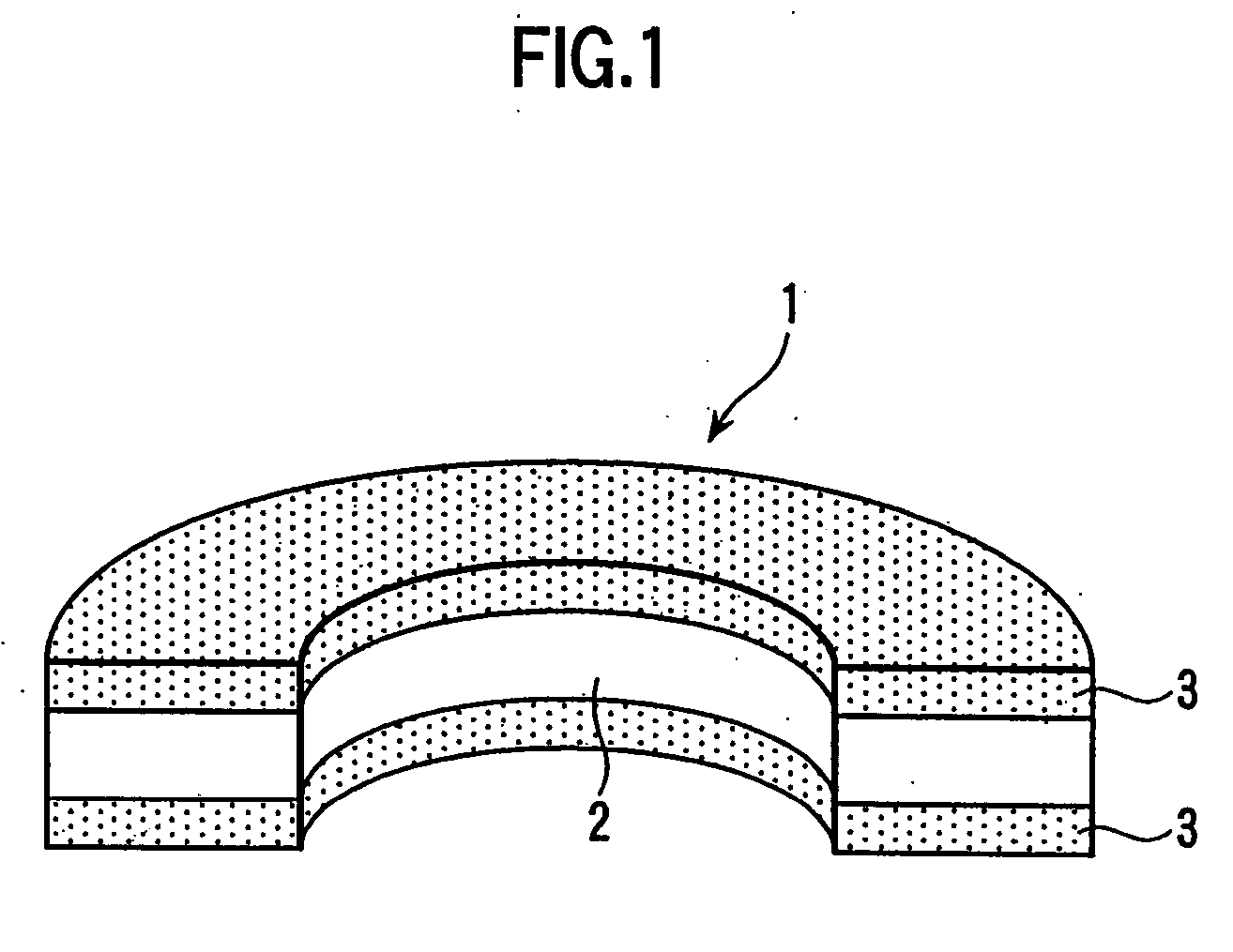
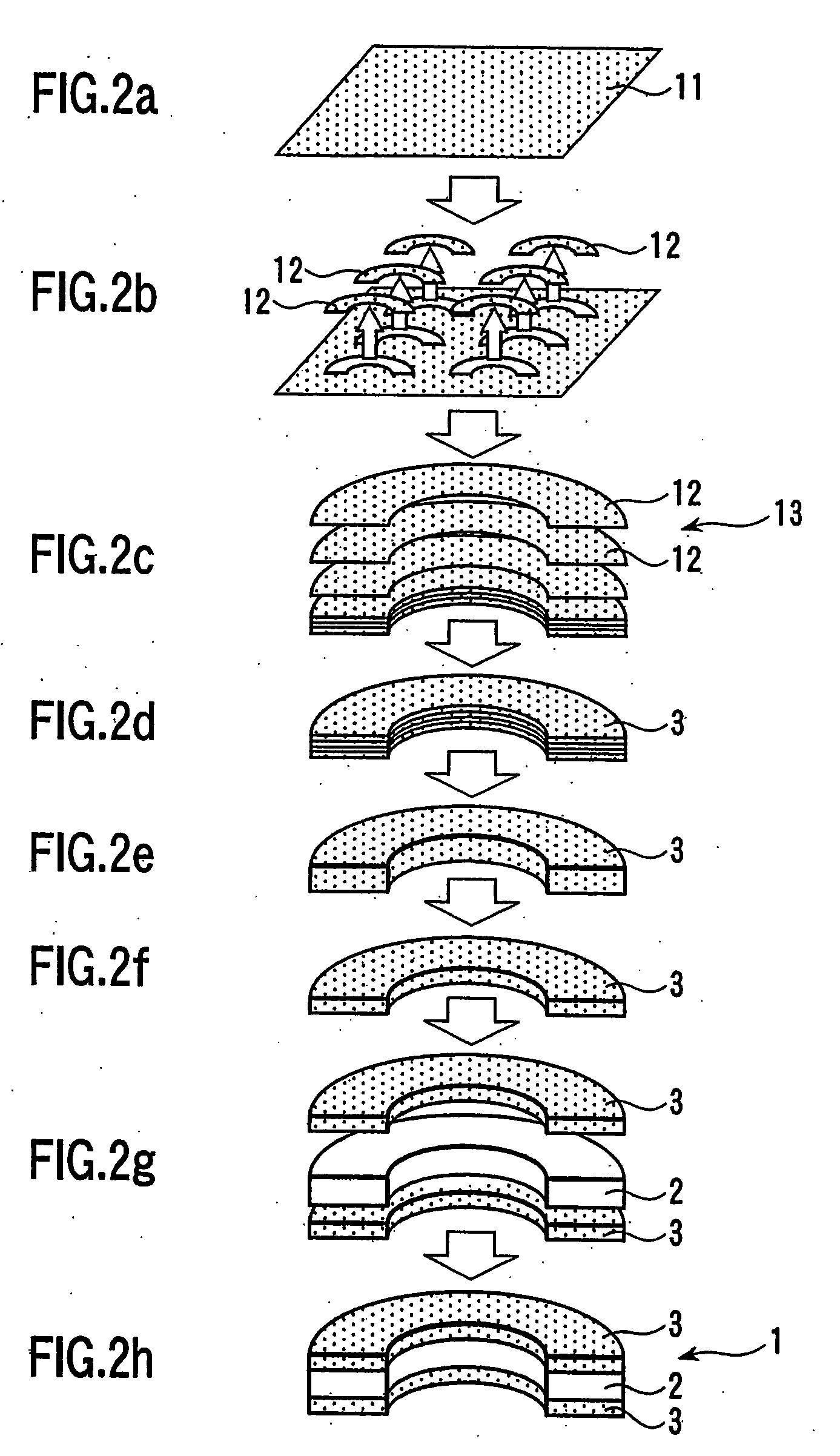
[0045]FIG. 3 and FIG. 4 are schematic views of a bearing housing structure having the preform 1 illustrated in FIG. 1. A bearing housing 17 is constituted by infiltrating aluminum alloy into the preform 1. A shaft 16 is supported by thus obtained two aluminum alloy castings 15 formed into MMC.

[0046] In case where the high Vf member 2 of the preform 1 is constituted by a stainless steel solid material SUS430 (JIS) and the low Vf member 3 is constituted by stainless steel filaments whose contents are 75%Fe-20%Cr-5%Si (weight %), the coefficient of linear expansion of the preform formed into MMC by aluminum alloy ADC12 (JIS) is 12.0×10⁻⁶ / ° C. In this case, an own coefficient of linear expansion of stainless steel filaments is 10.8×10⁻⁶ / ° C.

[0047] Accordingly, in case where the shaft 16 is made of iron base material S48C (JIS) whose coefficient of linear expansion is 11.7×10⁻⁶ / ° C., since the difference of coefficients of linear expansion between the shaft 16 and the bearing housing 17...

second embodiment

[0048]FIG. 5a and FIG. 5b show a bearing housing structure having the preform according to the present invention. In this example, the bearing housings are incorporated onto a cylinder block of a horizontally opposed four cylinder engine. The cylinder block is made of aluminum alloy (for example ADC12) casting, being divided into a left cylinder block 21 and a right cylinder block 22 which are independently cast, respectively. A plurality of left bearing housings 23 respectively having a semicircular groove are formed in the left cylinder block 21. Similarly, a plurality of right bearing housings 24 having a semicircular groove are formed in the right cylinder block 22.

[0049] A crankshaft 25 is held between the left bearing housings 23 and the right bearing housings 24 and is supported by the respective grooves of these bearing housings 23, 24. The crankshaft 25 which is formed by steel (for example S48C) rotates in the grooves while the bearing housings 23, 24 are subjected to larg...


PUM

PropertyMeasurementUnit
thicknessaaaaaaaaaa
thicknessaaaaaaaaaa
thicknessaaaaaaaaaa

Abstract

When a cylinder block is cast, a bearing housing is constituted by a preform integrally cast with the cylinder block. In order to raise the strength of the bearing housing, a metal matrix composite is formed around the preform. The preform is constituted by a high volume factor member having a relatively high volume factor and two low volume factor members having a relatively low volume factor connected with top and under surfaces of the high volume factor member respectively. The high volume factor member is made of solid metal and the low volume factor member is made of sintered metal filaments. Base material of the cylinder block infiltrates into the low volume factor member to form a metal matrix composite in the preform.

Description

[0001] This application is a Divisional of U.S. Pat. application Ser. No. 10 / 388,467, filed Mar. 17, 2003 and is incorporated herein by reference in its entiretyBACKGROUND OF THE INVENTION [0002] 1. Field of the Invention [0003] The present invention relates to the method of manufacturing a preform used for forming Metal Matrix Composite (MMC) and a bearing housing structure having the preform of a cylinder block of an internal combustion engine. [0004] 2. Discussion of Related Arts [0005] Generally, cylinder blocks made of cast aluminum alloy are widely used for automobile engines. As shown schematically in FIG. 7 and FIG. 8, a crank journal 52 is supported by a bearing housing 51 of a cylinder block 50. The crank journal 52 is made of forged steel, for example S48C (symbol of grade according to Japanese Industrial Standard Material Specification; hereinafter referred to as JIS) (coefficient of linear expansion: 11.7×10⁻⁶ / ° C.) and the bearing housing 51 is made of cast aluminum al...

Claims


Application Information

Patent Timeline
Patent Type & Authority Applications(United States)
IPC IPC(8): B32B5/02C22C47/20B22D19/14B22F7/00B22F7/08C22C47/06C22C49/06F16C9/02
CPCB22D19/14B22F7/004B22F7/08B22F2999/00F16C9/02Y10T428/12444Y10T428/12236B22F3/002B22F3/26
Inventor ODA, TERUYUKIKATSUYA, AKIHIROSHIRAISHI, TOHRU
Owner ODA TERUYUKI
Why Eureka
Try Eureka