Fuel cell system

a fuel cell and system technology, applied in the direction of battery/fuel cell control arrangement, cell components, electric devices, etc., can solve the problem that the previously known system meets these requirements only inadequately, and achieve the effect of improving the availability and reliability of the system

Active Publication Date: 2006-03-02
ROBERT BOSCH GMBH
View PDF3 Cites 6 Cited by
  • Summary
  • Abstract
  • Description
  • Claims
  • Application Information

AI Technical Summary

Benefits of technology

[0004] It is therefore an object of the invention to propose a fuel cell system which has improved availability and reliability of the system, compared to the prior art.

Problems solved by technology

Previously known systems meet these requirements only inadequately.

Method used


Image

  • Fuel cell system
  • Fuel cell system
  • Fuel cell system

Examples


Embodiment Construction

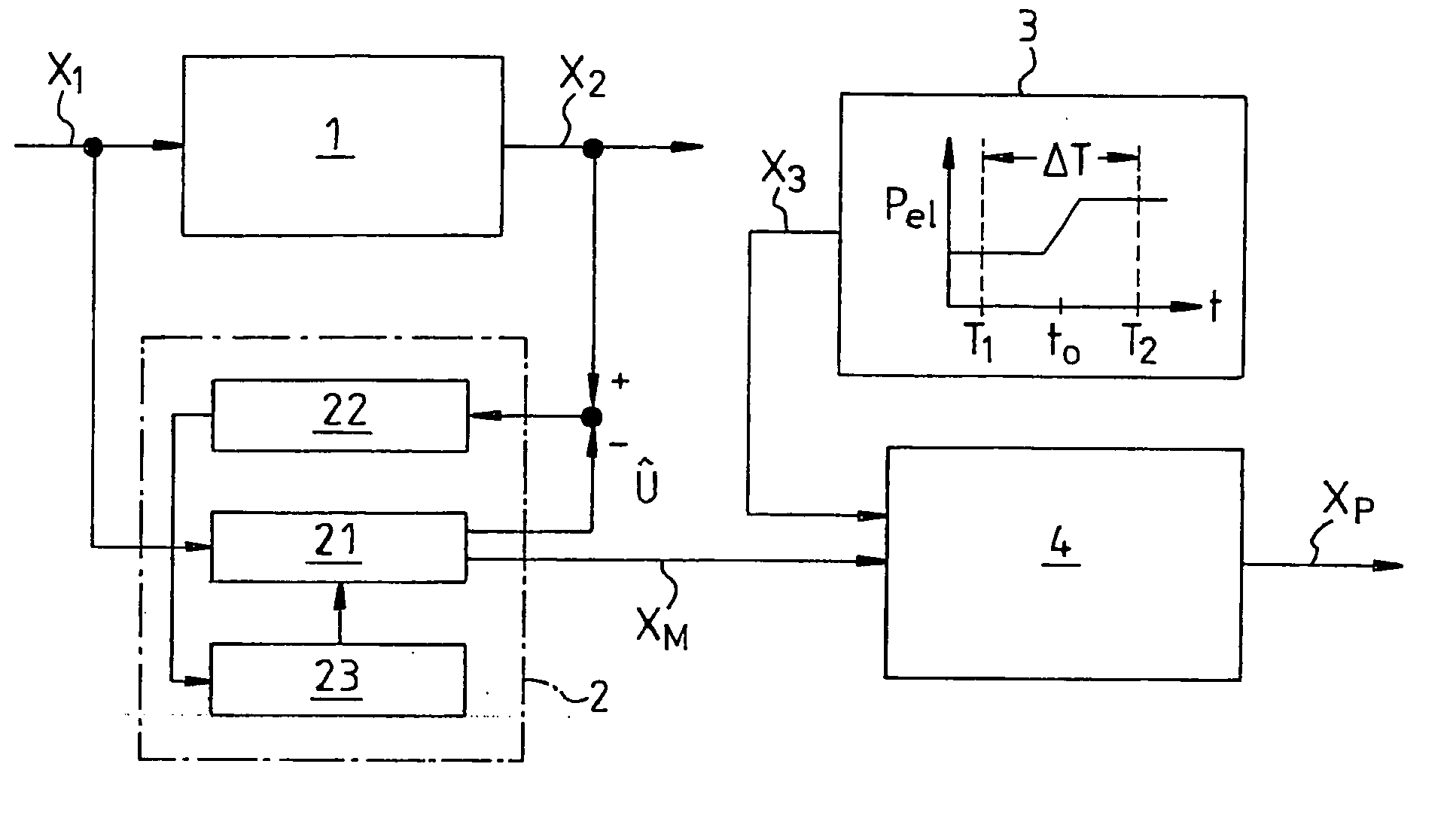
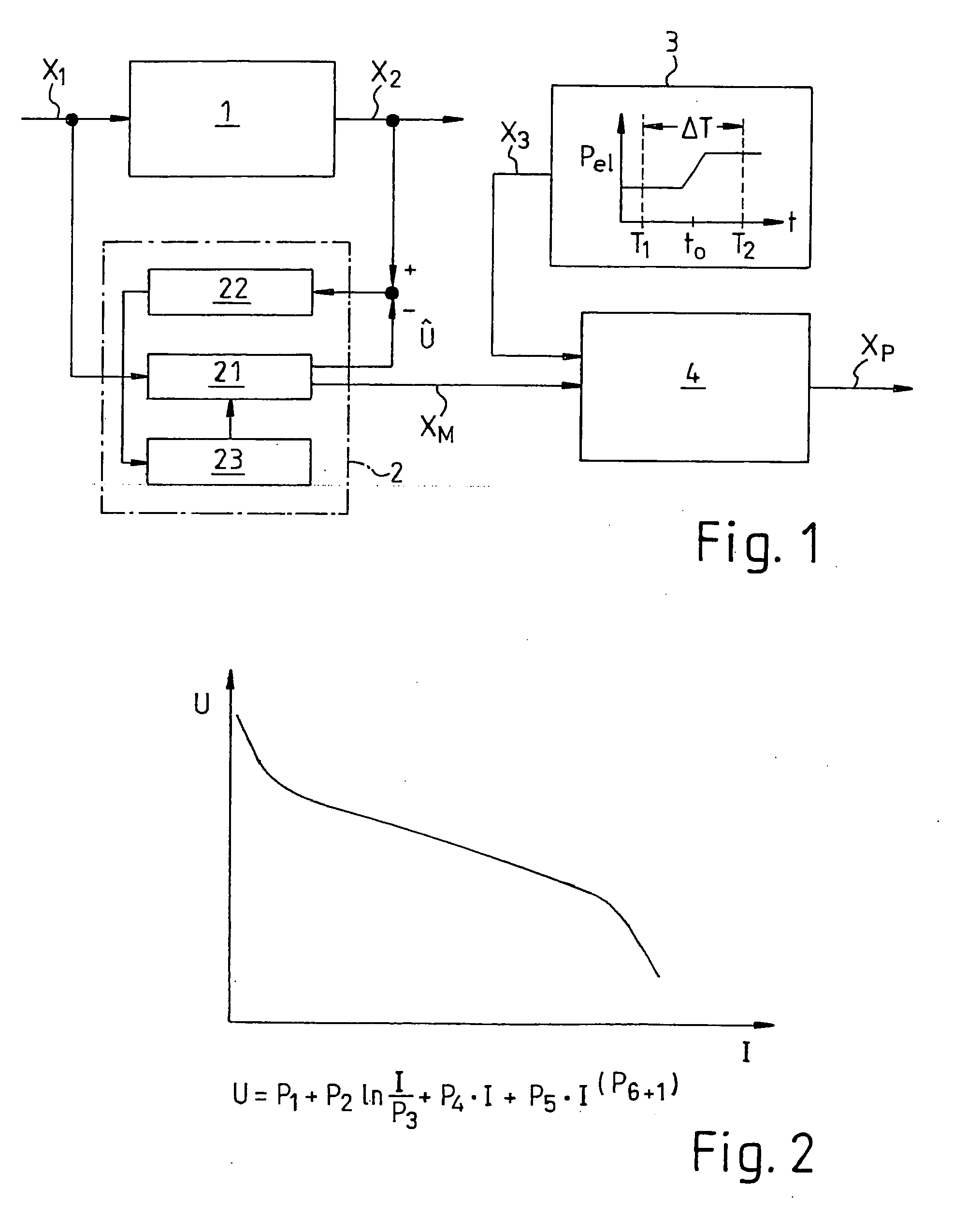
[0061] In FIG. 1, part of a fuel cell system according to the invention is shown schematically as a block circuit diagram. A fuel cell unit 1 or fuel cell stack 1 has one or more input parameters X1 and one or more output parameters X2. The input parameters X1 are for instance parameters of mass flows, temperatures, electrical currents, and / or pressures of the fuel cell system. An output parameter X2 of the fuel cell 1 is for instance a voltage. In terms of the invention, the input and output parameters X1, X2 may be embodied as so-called base parameters. Moreover, the output parameter X2 can be embodied as a so-called second parameter according to the invention. In this last case, the actual voltage X2lst at an instantaneous time T1, and / or an expected or potential voltage X2pot at a time T2 that is later by a time difference ΔT, can be compared with a predetermined set-point value for the voltage X2Soll, or with the electrical minimum voltage X2min of the fuel cell unit 1.

[0062] ...


PUM

PropertyMeasurementUnit
poweraaaaaaaaaa
constant electrical power PMaaaaaaaaaa
electrical poweraaaaaaaaaa

Abstract

A fuel cell system has at least one fuel cell unit for generating electrical energy, a unit for storing or dispensing electrical energy, an electrical consumer for consuming electrical energy, a diagnostic unit for ascertaining a functional capability of the at least one fuel cell unit during a diagnosis phase, and a control unit for determining an electrical power generated at least during the diagnosis phase by the at least one fuel cell unit.

Description

BACKGROUND OF THE INVENTION [0001] The invention relates to a fuel cell system. [0002] In the use of fuel cell systems, for instance as so-called APUs (auxiliary power units) and / or in vehicle drive systems as well as in stationary systems, the electrical energy management should be aware of the status of the fuel cell or fuel cell stack with regard to dynamics, performance, degradation, and / or minimum voltage. Especially in reformer systems, information is additionally required about the degradation and the dynamics of the gas generating unit. Only then can the availability and reliability of the system be assured. [0003] Previously known systems meet these requirements only inadequately. For instance, U.S. Pat. No. 5,945,229 describes a fuel cell system in which the behavior of the current / voltage characteristic curve of the stack is ascertained via additional fuel cells at the stack inlet and the stack outlet. From this, the CO concentration in the hydrogen-rich anode gas is dete...

Claims


Application Information

Patent Timeline
Patent Type & Authority Applications(United States)
IPC IPC(8): H01M8/00
CPCB60L3/0053H01M8/04313H01M8/04365H01M8/0438H01M8/04589H01M8/04679Y02T90/34H01M8/04947H01M8/04985H01M8/04992H01M16/003Y02E60/50H01M8/0494H01M8/04953B60L58/30Y02T90/40
Inventor BINDER, JUERGENSCHOCH, EBERHARDGOTTWICK, ULRICHSALIGER, RAINERWIEDEMANN, GUNTERBAUMANN, FRANKSCHAEFERT, ARTHURINTORP, JENSGRAEHN, JAN-MICHAEL
Owner ROBERT BOSCH GMBH
Why Eureka
Try Eureka