Electrically variable transmission with selective fixed ratio operation

a transmission and ratio technology, applied in the direction of electric propulsion mounting, transportation and packaging, gearing, etc., can solve the problems of low fuel consumption, achieve the best possible energy efficiency and emissions, enhance the transmission operation, and optimize the ratio coverage

Inactive Publication Date: 2006-03-02
GM GLOBAL TECH OPERATIONS LLC
View PDF7 Cites 109 Cited by
  • Summary
  • Abstract
  • Description
  • Claims
  • Application Information

AI Technical Summary

Benefits of technology

[0016] The present invention improves upon the above-referenced prior art transmissions by providing additional clutches to enhance operation of the transmission, to allow additional fixed speed ratios and to allow an additional compound-power-split speed ratio range. An object of the invention is to provide the best possible energy efficiency and emissions for a given engine. In addition, optimal performance, capacity, package size, and ratio coverage for the transmission are sought.

Problems solved by technology

Fixed ratio operation may also result in lower fuel consumption when operating under conditions where engine speed can approach its optimum without using the motor / generators.

Method used


Image

  • Electrically variable transmission with selective fixed ratio operation
  • Electrically variable transmission with selective fixed ratio operation
  • Electrically variable transmission with selective fixed ratio operation

Examples


embodiment 10

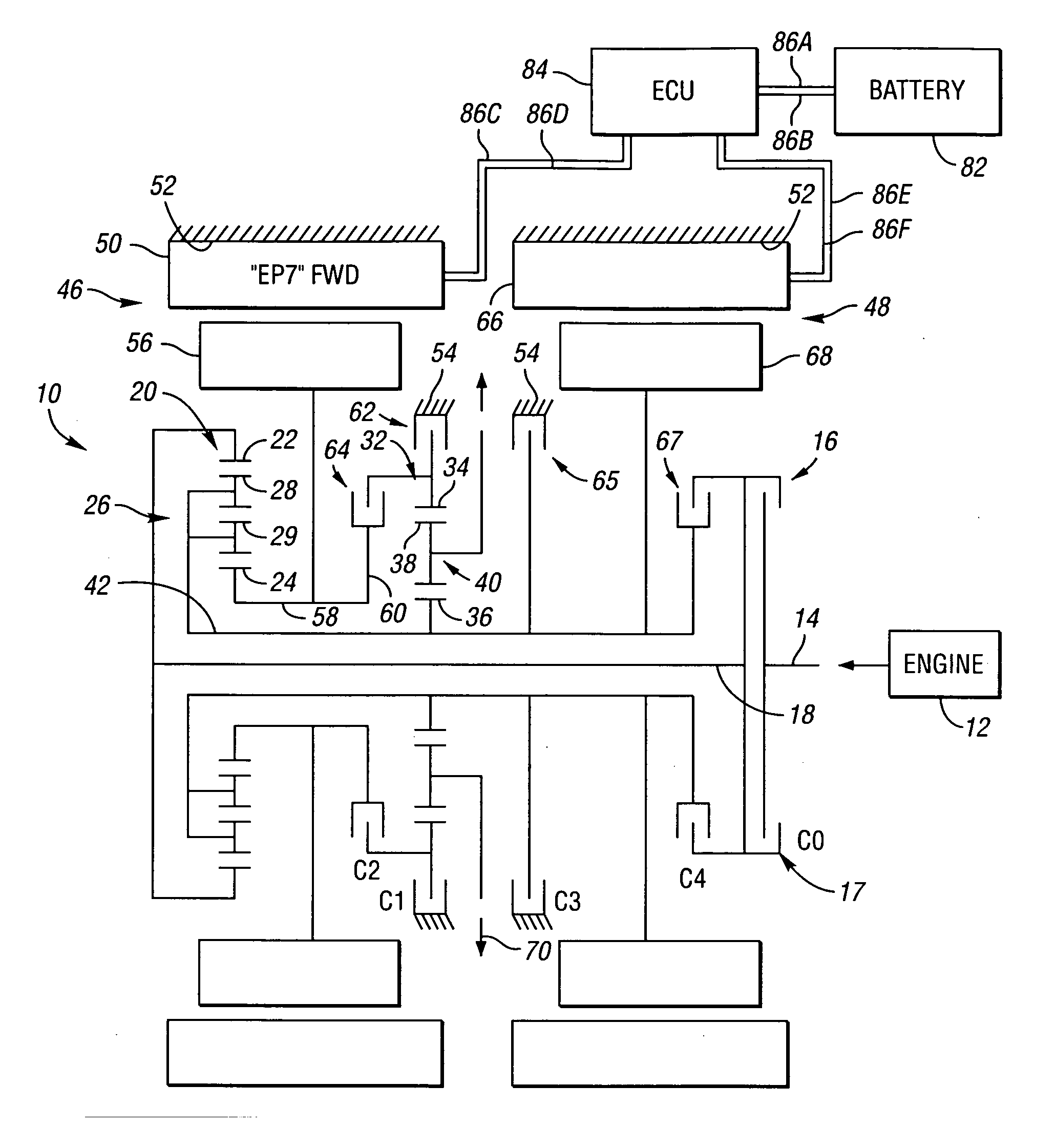
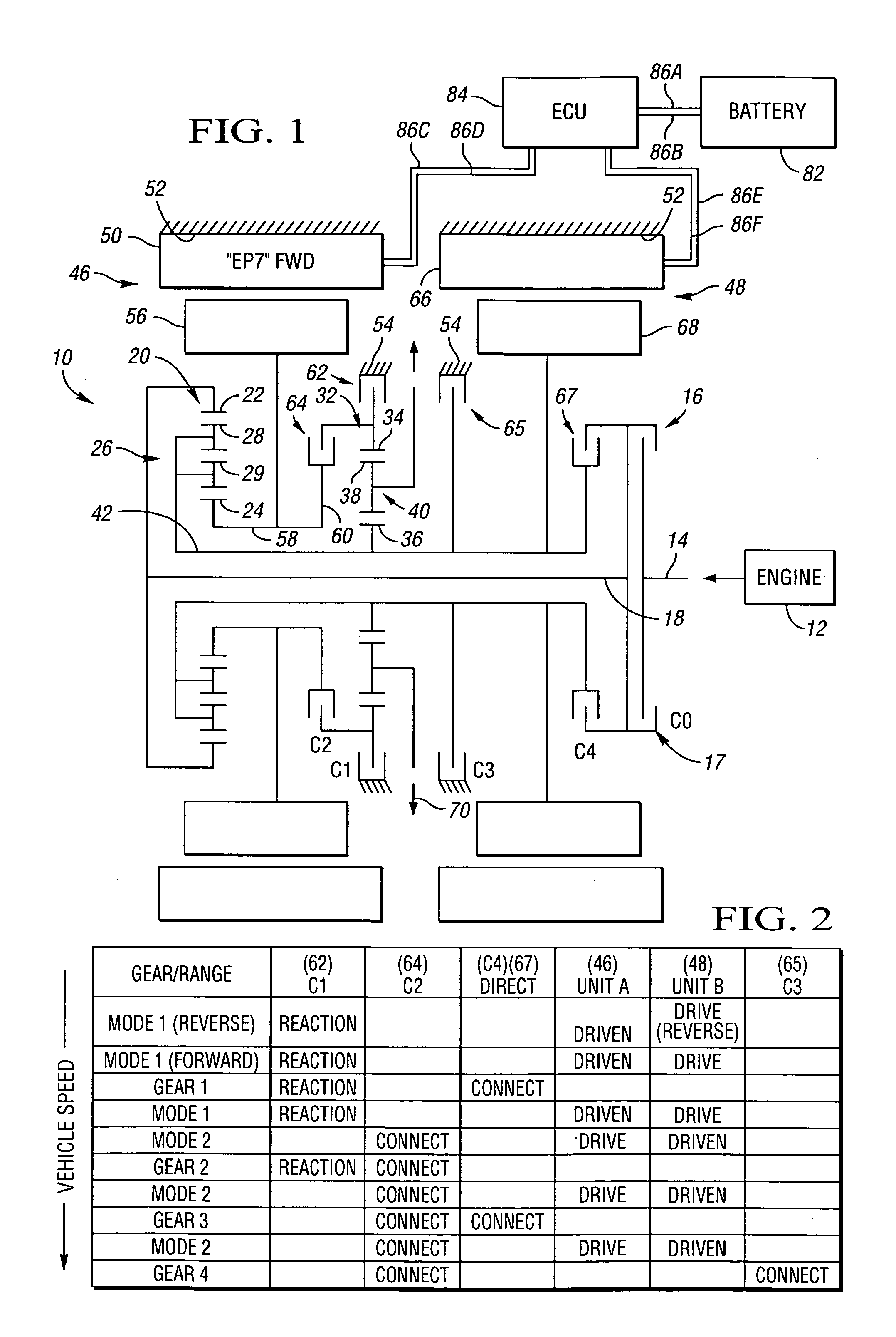
[0052] The first preferred embodiment 10 also incorporates first and second motor / generators 46 and 48, respectively. The stator 50 of the first motor / generator 46 is secured to the generally annular, interior surface 52 of the transmission housing 54. The rotor 56 of the first motor / generator 46 is secured to a sleeve shaft 58. The inner, sun gear 24 of the first planetary gear set 20 secured to the forward end of the sleeve shaft 58, and the opposite end of the sleeve shaft 58 terminates in a radially extending flange plate 60 which constitutes an interface with a clutch means, which is hereinafter described.

[0053] The stator 66 of the second motor / generator 48 is also secured to the generally annular, interior surface 52 of the transmission housing 54. The rotor 68 of the second motor / generator 48 is secured to the central shaft 42, and as such the first and second planetary gear sets 20 and 32 are further compounded.

[0054] The two planetary gear sets 20 and 32 as well as the tw...

embodiment 110

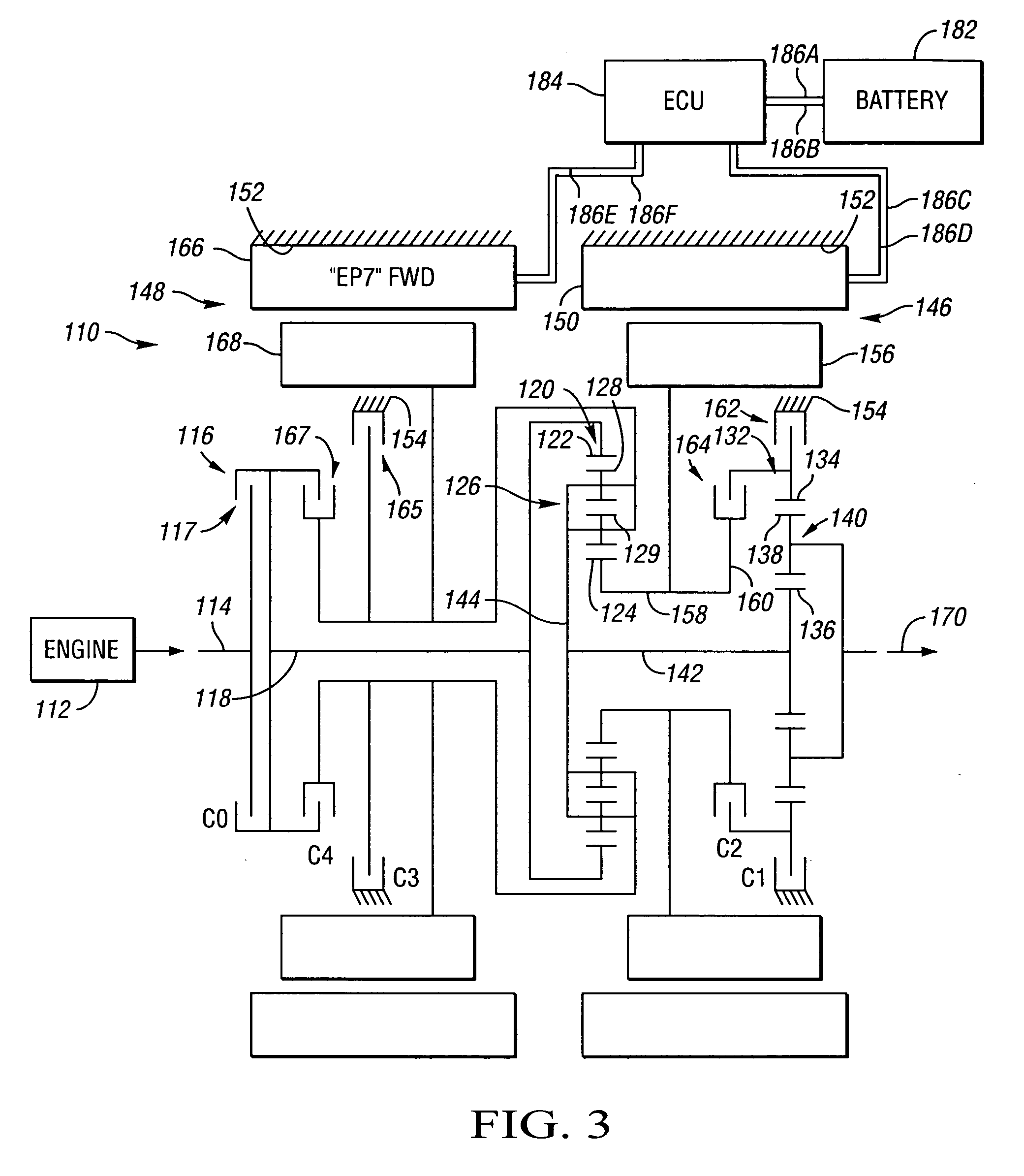
[0095] The second preferred embodiment 110 also incorporates first and second motor / generators 146 and 148, respectively. The stator 150 of the first motor / generator 146 is secured to the generally annular, interior surface 152 of the transmission housing 154. The rotor 156 of the first motor / generator 146 is secured to a sleeve shaft 158. The inner, sun gear 124 of the first planetary gear set 120 is also secured to the sleeve shaft 158.

[0096] The ring gear 134 of the second planetary gear set 132 may be selectively grounded to the housing 154, as by a first torque transfer device 162 (C1). That is, the grounded ring gear 134 is selectively secured against rotation by an operative connection to the non-rotatable housing 154. The ring gear 134 of the second planetary gear set 132 is also selectively connected to the radially extending flange plate 160, as by a second torque transfer device 164 (C2). The first and second torque transfer devices 162 and 164 are employed to assist in t...


PUM


Abstract

An electrically variable transmission includes: an input member to receive power from an engine; an output member; first and second motor/generators; and first and second differentially geared planetary gear sets each having first, second and third gear members. The input member is continuously connected to the first member of the first planetary gear set, and the output member is continuously connected to the first member of the second planetary gear set. The first motor/generator is continuously connected to the second member of the first planetary gear set, and selectively connected to the second member of the second planetary gear set. The second motor/generator is continuously connected with the third member of the second planetary gear set. Five or six torque transfer devices selectively connect members of the planetary gear sets with each other or with ground. The torque transfer devices are engageable in combinations of two or three to provide five or six available fixed speed ratios.

Description

CROSS-REFERENCE TO RELATED APPLICATION [0001] This application claims the benefit of U.S. Provisional Application 60 / 606,359, filed Sep. 1, 2004, which is hereby incorporated by reference in its entirety.TECHNICAL FIELD [0002] The present invention relates to electrically variable transmissions with selective operation both in power-split variable speed ratio ranges and in up to six fixed speed ratios. BACKGROUND OF THE INVENTION [0003] Internal combustion engines, particularly those of the reciprocating piston type, currently propel most vehicles. Such engines are relatively efficient, compact, lightweight, and inexpensive mechanisms by which to convert highly concentrated energy in the form of fuel into useful mechanical power. A novel transmission system, which can be used with internal combustion engines and which can reduce fuel consumption and the emissions of pollutants, may be of great benefit to the public. [0004] The wide variation in the demands that vehicles typically pl...

Claims


Application Information

Patent Timeline
Patent Type & Authority Applications(United States)
IPC IPC(8): F16H3/72B60K6/365B60K6/387B60K6/445B60K6/48
CPCB60K1/02Y02T10/6239B60K6/387B60K6/445B60K6/48F16H3/728F16H2037/0866F16H2037/088F16H2037/104F16H2037/106F16H2200/0043F16H2200/0047F16H2200/0052F16H2200/2007Y02T10/6221B60K6/365Y02T10/62
Inventor HOLMES, ALAN G.SCHMIDT, MICHAEL R.KLEMEN, DONALDHENDRICKSON, JAMES D.SOWUL, HENRYK
Owner GM GLOBAL TECH OPERATIONS LLC
Why Eureka
Try Eureka