Friction engaging device

a friction engaging and device technology, applied in the direction of couplings, transportation and packaging, gearing, etc., can solve the problems of the decline of the friction coefficient, and achieve the effect of reducing or excluding the iron component, ensuring the strength of the friction engaging member, and easy formation of the surface layer

Inactive Publication Date: 2006-03-02
GKN DRIVELINE TORQUE TECHNOLOGY KK
View PDF17 Cites 34 Cited by
  • Summary
  • Abstract
  • Description
  • Claims
  • Application Information

AI Technical Summary

Benefits of technology

[0016] In accordance with one or more embodiment of the present invention, a friction engaging member may be formed of a steel product containing an iron component. Therefore, it is possible to secure the strength of a friction engaging member and to easily reduce or exclude an iron component by heat treatment, deposition, painting, plating, and reforming a connective tissue of a surface of a steel product.
[0017] In accordance with one or more embodiments of the present invention, the surface layer may be subjected to surface treatment. Therefore, it is possible to easily form the surface layer.
[0018] In accordance with one or more embodiments of the present invention, the surface treatment may be a nitriding treatment. Therefore, it is possible to reliably suppress chemical adsorption of a friction adjuster.
[0019] In accordance with one or more embodiments of the present invention, the friction engaging device may be provided in a driving path of a vehicle. Therefore, it is possible to set the absolute rotation number or the relative rotation number of a pair of rotation members (that is, a pair of friction engaging members) of the friction engaging device to be low, compared to the driving rotation number of a motor. As the upper limit of a rising temperature of a lubricant can be controlled, it is possible to set a lower temperature area. That is, it is possible to use the friction engaging device in an area having high transmission torque.
[0020] In accordance with one or more embodiments of the present invention, the friction engaging member may be provided to apply or release the torque between an outer differential case and an inner differential case of a differential device having the outer differential case and the inner differential case capable of relatively rotating to the inside and the outside. Therefore, the torque transmitted to the outer differential case of the differential device is reliably transmitted to the inner differential case via the friction engaging members, and thus the torque which has passed through the differential device can be securely transmitted.
[0021] In accordance with one or more embodiments of the present invention, one side of the friction engaging members is a friction plate formed of the steel product and the other side thereof is a friction plate having a friction material on the surface. Therefore, a chemical adsorption surface is confined to one plate by a surface layer of one side and a friction material of the other side, so as to securely suppress chemical adsorption of a friction adjuster in a friction coupling surface of a friction plate formed of the steel product.

Problems solved by technology

Therefore, because the FM material included in a lubricant is chemically adsorbed into the surface of the outer plate made of the SC material and the surface thereof is activated, depending on a temperature environment, there is a problem in which a friction coefficient thereof is declined.

Method used


Image

  • Friction engaging device
  • Friction engaging device
  • Friction engaging device

Examples


first embodiment

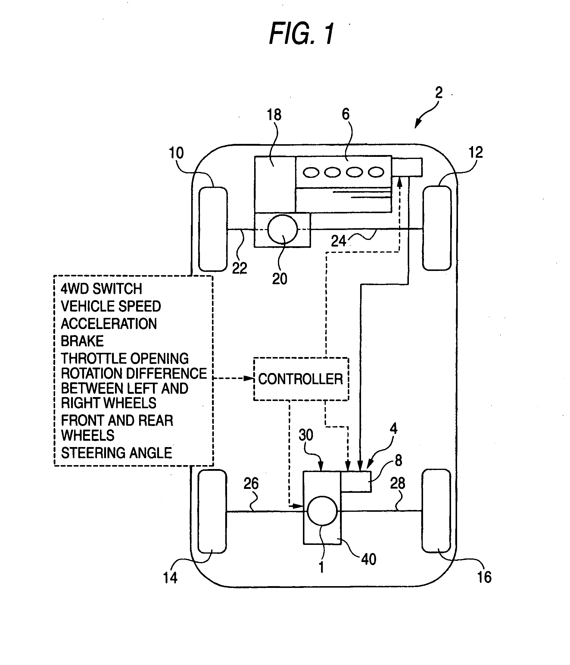
[0032]FIG. 1 is a top plan view illustrating a skeleton of an electric assist type car 2 to which a rear differential device 1 that is a friction engaging device according to a first embodiment of the present invention is applied. The friction engaging device is applied to, for example, an electric motor driving device 4 of the car 2.

[0033] A main driving source of the car 2 is an engine 6 that is an internal combustion engine and a sub-driving source thereof is an electric motor 8. The engine 6 drives front right and left wheels 10 and 12 (primary driven wheels 10 and 12) and the electric motor 8 drives rear right and left wheels 14 and 16 (auxiliary driven wheel 14 and 16). The output of the engine 6 is transmitted to the front wheels 10 and 12 through a transmission 18 and then through a front differential device 20 that is a differential device, and then through right and left axle shafts 22 and 24. The transmission 18 is disposed in a housing adjacent to the engine. The electr...

second embodiment

[0063] The present invention may be applied to a coupling arranged in the input side of a final reducer (employing the pair of reduction gears composed of a pair of bevel gears, as a general structure) of the differential device.

[0064] As shown in FIG. 5, a coupling 1A that is a friction engaging device of a car 2A transmits a drive force from an engine 6 to a rear differential device 34. That is, a drive force is transmitted to front right and left wheels 10 and 12 through a front differential device 20 and right and left axle shafts 22 and 24 from the engine 6. Further, a drive force is transmitted to the coupling 1A through the pair of direction conversion gears 32 from the differential case of the front differential device 20. The differential device 34 is disposed in a housing 40 individually and separately mounted from a housing accommodating the transmission 18 adjacent to the engine 6.

[0065] The coupling 1A is similarly structured with the applying / releasing device 7 in th...


PUM


Abstract

An outer plate 31, which is used under a lubricated environment of a differential gear oil including a friction adjuster, is made of a SC tempered material which is subjected to nitriding treatment to suppress chemical adsorption of the friction adjuster. An inner plate 33 has paper on a surface thereof. The outer plate 31 and the inner plate 33 are provided to apply or release the torque between an outer differential case 3 and an inner differential case 5 of a rear differential device 1 having the outer differential case 3 and the inner differential case 5 capable of relatively rotating to the inside and the outside.

Description

[0001] The present application claims foreign priority based on Japanese Patent Application No. P.2004-251743, filed on Aug. 31, 2004, the contents of which are incorporated herein by reference. BACKGROUND OF THE INVENTION [0002] 1. Field of the Invention [0003] The present invention relates to a friction engaging device which is used for applying or releasing a torque supplied from a driving force source. [0004] 2. Related Art [0005] Disclosed in JP-A-2003-113874 is a friction engaging device applied to an electric motor driving device. The electric motor driving device decelerates an output of an electric motor and transmits the decelerated output to right and left axle shafts for driving rear right and left wheels. An electric motor is used as a sub-driving source. Front wheels use an engine such as an internal combustion engine as a main driving source, thus front right and left wheels are driven by the engine. [0006] In the electric motor driving device, a first power transmiss...

Claims


Application Information

Patent Timeline
Patent Type & Authority Applications(United States)
IPC IPC(8): F16H48/06
CPCB60K23/0808F16D27/004F16H48/30F16D2300/10F16H48/22F16D27/115
Inventor AIKAWA, MASASHI
Owner GKN DRIVELINE TORQUE TECHNOLOGY KK
Why Eureka
Try Eureka