Method of using a shielded tip catheter

a technology of shielded tip and catheter, which is applied in the direction of multi-lumen catheter, catheter, intravenous device, etc., can solve the problems of only being able to achieve the effect of cutting off blood flow through, reducing the amount of blood being dialized, and facilitating the passage of guide wires

Inactive Publication Date: 2006-03-02
MEDICAL COMPONENTS INC
View PDF18 Cites 52 Cited by
  • Summary
  • Abstract
  • Description
  • Claims
  • Application Information

AI Technical Summary

Benefits of technology

[0007] Briefly, the present invention provides a multilumen catheter assembly. The assembly includes an elongated tubular body, divided by a sidewall extending throughout the center of the tube, dividing the tube into two generally “D-shaped” lumens, of which the distal openings are at unequal lengths. The most distal tip is round and non-tapered with an oval side opening just proximal to the distal opening to facilitate guide wire passage. The shorter, more proximal undercut lip lumen has a single oval side hole opening directly centered just proximal to the center of the undercut (overhanging) lip. The two oval side holes facilitate passage of a guide wire for insertion. The shorter lumen (the arterial or aspiration port) connects through a connecting hub assembly to allow oblique connection of an arterial (generally red color coded) port luer-lock connection tube. The longer lumen (the venous or return port) connection in the hub assembly in a straight-through direction for connection to the venous (generally blue color coded) luer-lock connection tube.
[0008] Additionally, the present invention provides a method of inserting a catheter assembly over a catheter guide wire. The guide wire is inserted from the tip of the longer (venous return) lumen, out the oval guide wire side hole parallel to the lumen and enters the shorter (arterial aspiration) lumen through the oval guide wire hole into the lumen of the aspiration port. The guide wire is then advanced through the length of the catheter to exit the red luer-lock connector. The catheter is then advanced over the guide wire for percutaneous insertion without a peel away sheath, thus minimizing the possibility of bleeding and air embolism. The course of the guide wire through the catheter tips allows an insertion course co-axial to the guide wire and provides that the overhanging undercut lip of the shorter port is folded down against the longer venous port to prevent difficult passage as the catheter passes through the venatory site.

Problems solved by technology

However, this technique is only possible in cases where the catheter is of a relatively small diameter, made of a stiff material, and not significantly larger than the guide wire, for example, for insertion of small diameter dual lumen catheters.
However, suction of the toxic blood into the arterial lumen may draw the distal opening of the arterial lumen against the wall of the blood vessel into which the lumen is inserted, reducing or cutting off blood flow through the arterial lumen, and significantly reducing the amount of blood being dialyzed.
However, neither Twardski et al. nor Davey et al. disclose a structure or method for inserting the catheter into the blood vessel that minimizes the likelihood of the overhanging lip from snagging on the blood vessel wall during insertion.

Method used


Image

  • Method of using a shielded tip catheter
  • Method of using a shielded tip catheter
  • Method of using a shielded tip catheter

Examples


Embodiment Construction

[0018] In the drawings, like numerals indicate like elements throughout. Certain terminology is used herein for convenience only and is not to be taken as a limitation on the present invention. The words “proximal” and “distal” refer to directions away from and closer to, respectively, the insertion tip of the catheter according to the present invention. The terminology includes the words above specifically mentioned, derivatives thereof, and words of similar import. The following describes preferred embodiments of the invention. However, it should be understood based on this disclosure, that the invention is not limited by the preferred embodiments described herein.

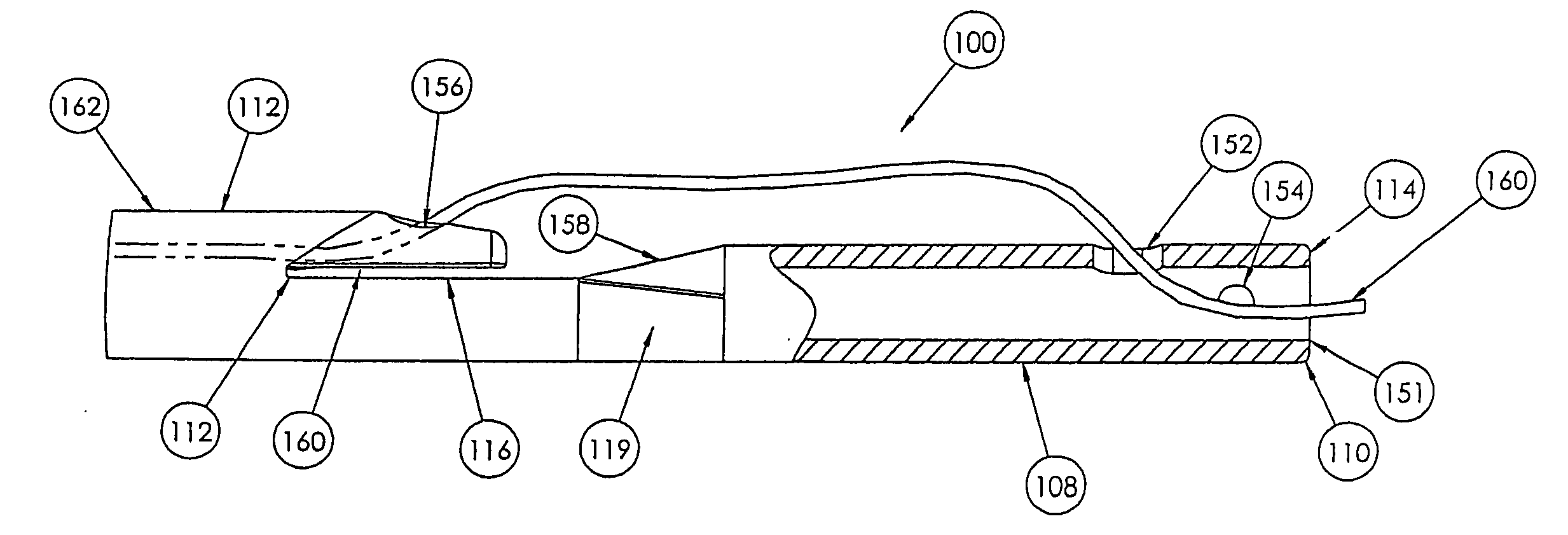
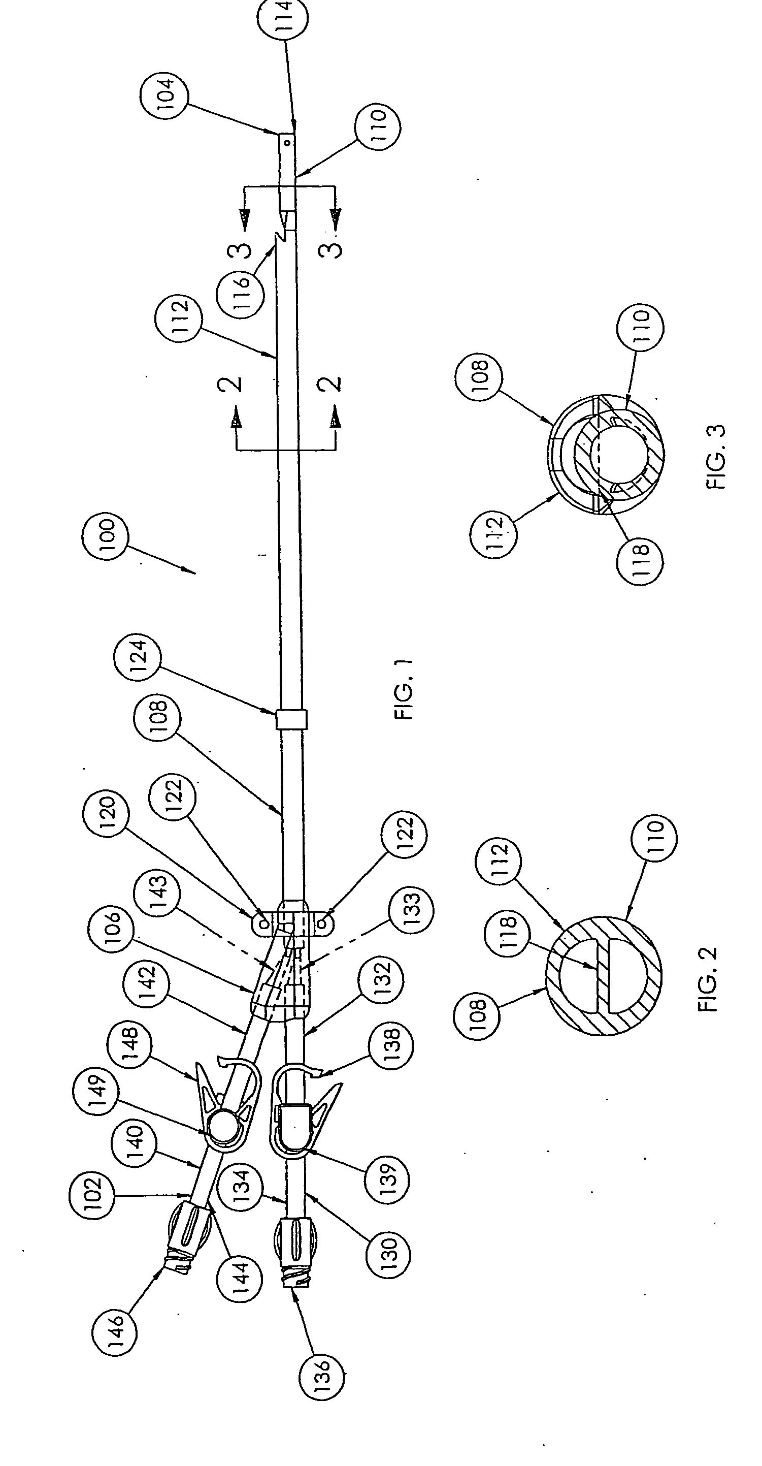
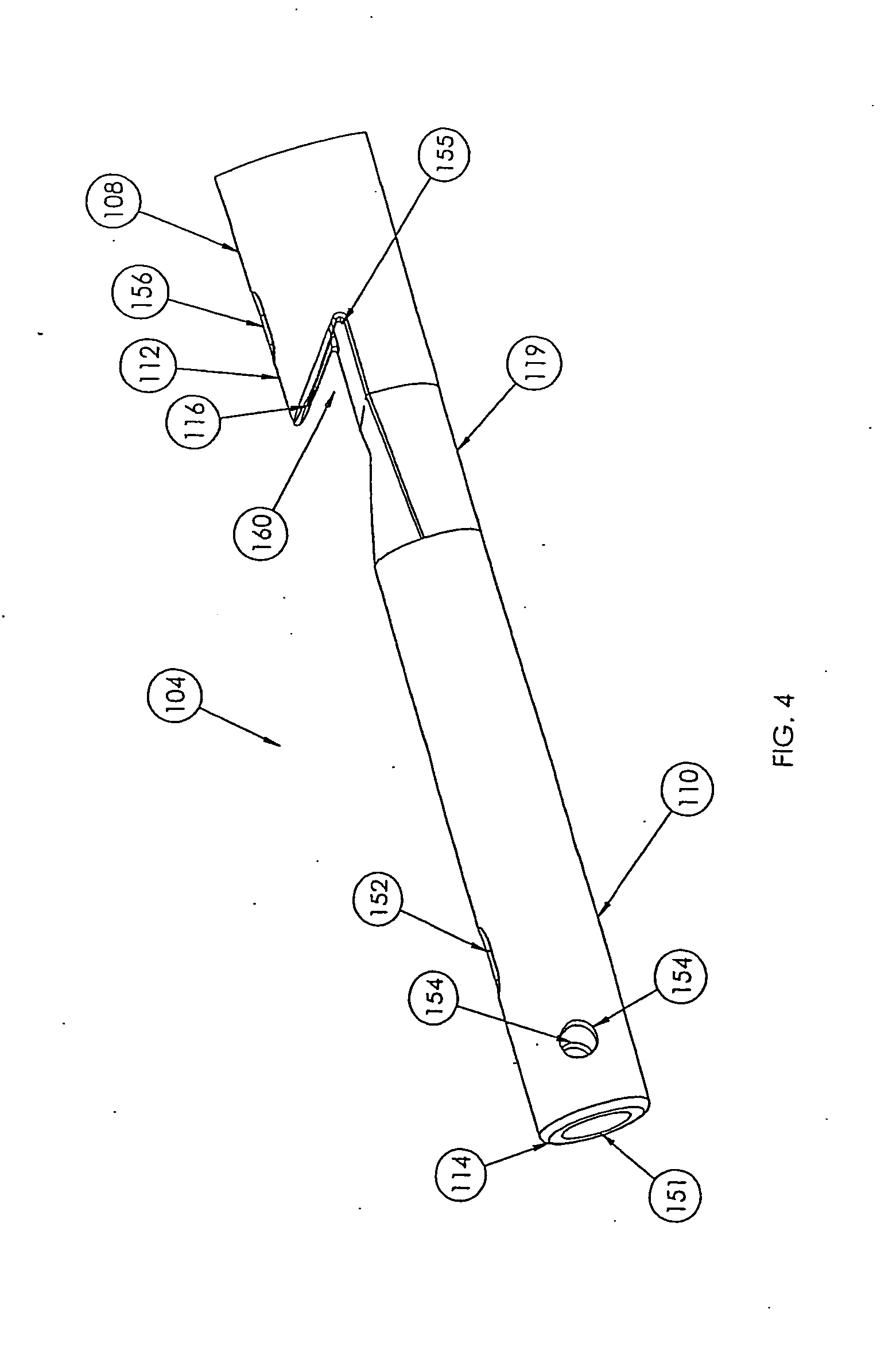
[0019] Referring now to FIG. 1, a side view of a catheter assembly 100 according to a preferred embodiment of the present invention is shown. The catheter assembly 100 includes a proximal end 102, a distal end 104, and a hub 106 connecting the proximal end 102 and the distal end 104. An elongated body 108 extends betwee...


PUM


Abstract

A multilumen catheter assembly is disclosed. The assembly includes an elongated body having a proximal end and a distal end and a first lumen having a sidewall extending between the proximal end and the distal end, a first distal opening disposed at the distal end, and a first guide wire opening disposed proximally of the distal end and co-planar with the sidewall. The assembly also includes a second lumen connected to the sidewall and extending from the proximal end toward the distal end, proximally of the distal end. The second lumen includes a second opening extending obliquely away from the sidewall distally toward the first distal opening and a second guide wire opening disposed proximally of the second opening and in a plane generally parallel to the sidewall. A method of inserting the catheter into a vessel is also disclosed.

Description

CROSS REFERENCE TO RELATED APPLICATIONS [0001] The present application claims the benefit of U.S. Provisional Patent Application Ser. No. 60 / 405,937, filed Aug. 23, 2002.FIELD OF THE INVENTION [0002] The present invention relates to a multilumen catheter assembly used to simultaneously withdraw and infuse a fluid to a body, such as during hemodialysis. BACKGROUND OF THE INVENTION [0003] Catheters for the introduction or removal of fluids may be placed in various venous locations and cavities throughout the body for introduction or removal of these fluids. Such catheterization may be performed by using a single catheter assembly having multiple lumens. A typical example of a multiple lumen catheter assembly is a dual lumen catheter in which one lumen introduces fluid and the other lumen removes fluid. Such a multiple lumen catheter assembly is known as the SPLIT STREAM™ catheter, manufactured and sold by Medical Components, Inc. of Harleysville, Pa. [0004] Generally, to insert any ca...

Claims


Application Information

Patent Timeline
Patent Type & Authority Applications(United States)
IPC IPC(8): A61M25/01
CPCA61M25/0029A61M25/003A61M2025/0037A61M25/007A61M2025/0031A61M25/0068
Inventor GATELY, NICHOLAS V.ARNOLD, W. PERRY
Owner MEDICAL COMPONENTS INC
Why Eureka
Try Eureka