
Dilation device

a tubular anatomy and pressure measurement technology, applied in the field of dilation devices, can solve the problems of severe post-operative dysphagia, dyspepsia, dysphasia and asthma, and the wrap around the oesophagus is too tight, so as to facilitate the initial passage and reduce or prevent damage to the surrounding tissue and structur

Inactive Publication Date: 2006-03-02
IMPERIAL INNOVATIONS LTD
View PDF18 Cites 3 Cited by
  • Summary
  • Abstract
  • Description
  • Claims
  • Application Information

AI Technical Summary

Benefits of technology

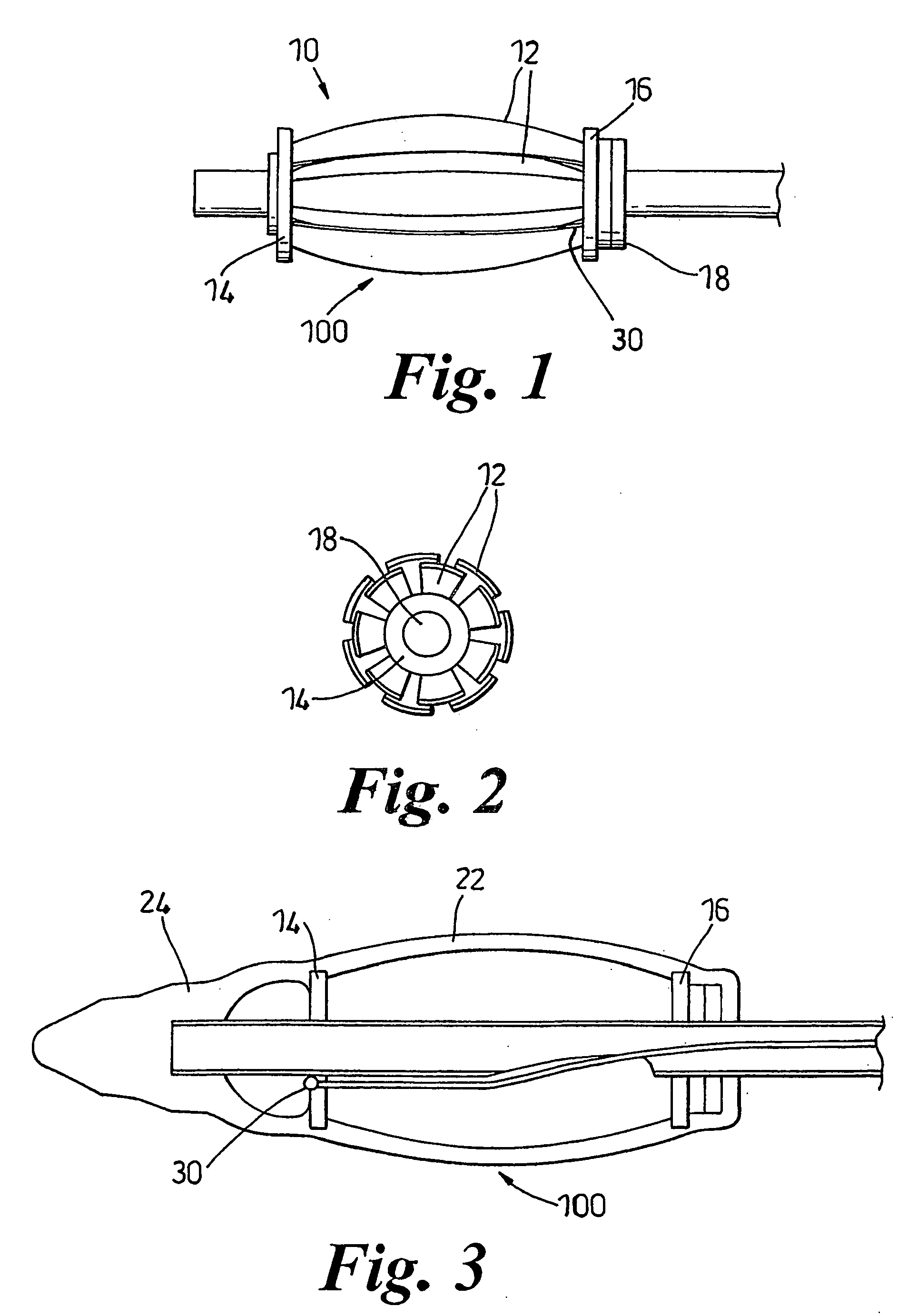
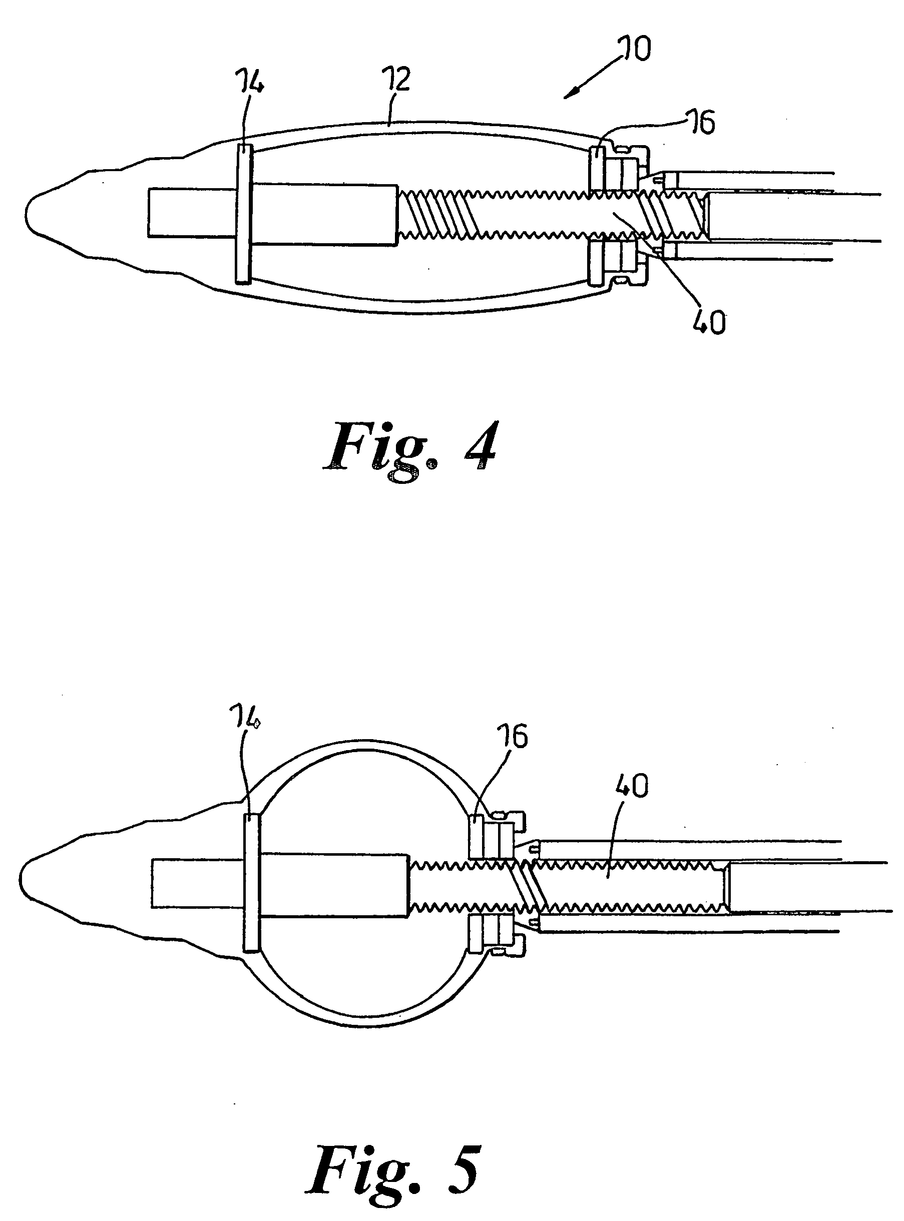
[0018] By means of the present invention, therefore, it is possible to achieve controlled dilation of a stricture in a tubular anatomy without having to use a plurality of devices each having a predetermined size. This in turn means that devices do not have to be taken in and out of the tubular anatomy, since once the device has been inserted, it can remain in place until the surgical operation or procedure is complete. This reduces the severity of dysphagia experienced after the operation or procedure.
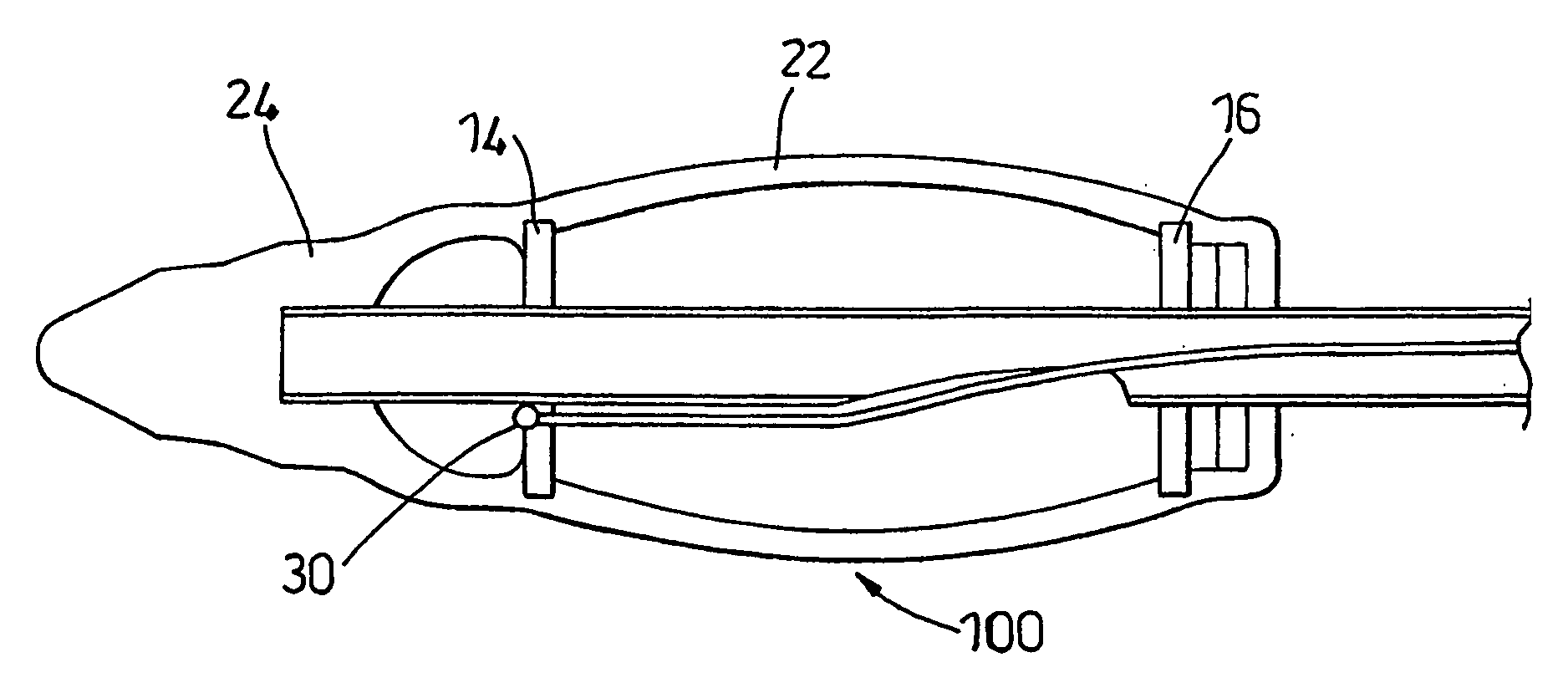
[0024] Conveniently the first and second connectors are substantially disc shaped. The device in its un-bowed state is therefore substantially cylindrical in shape. This ensures easy insertion into a tubular anatomy.
[0027] The presence of the at least one pressure sensor means the device according to the invention is able to cause dilation of a stricture in a tubular anatomy and also carry out oesophageal manometry. This means that it is not necessary to insert a separate manometer into the tubular anatomy, further reducing the severity of any dysphagia experienced by the patient.
[0031] Advantageously, the device further comprises an outer sleeve extending over the active element. This allows smooth passage of the device through the tubular anatomy. The outer sleeve may be made from any suitable material, but preferably it is made from rubber.
[0034] Preferably, the device further comprises a cone at the distal end of the active element. The cone facilitates initial passage though a stricture and reduces or prevents damage to the surrounding tissue and structure of the tubular anatomy.

Problems solved by technology

The presence of one or more strictures in an oesophagus may lead to problems and clinical conditions such as dyspepsia, dysphasia and asthma.
Surgery of the oesophagus, particularly conventional or laparoscopicfundoplication used in the treatment of gastroesophageal reflux disease can result in severe post-operative dysphagia.
This is because the wrap (i.e. the stomach wall wrapped around the oesophagus) is too tight.

Method used


Image

  • Dilation device
  • Dilation device
  • Dilation device

Examples


Embodiment Construction

[0045] Referring to the figures a device according to the present invention is designated generally by the reference numeral 10. The device can be used in, for example, an oesophageal manometry and also for the measurement of dilation within a tubular anatomy such as the oesophagus. The device may also be used to dilate strictures within the oesophagus.

[0046] The invention will be described in terms of use within oesophagus of a human or animal. However, it would also be a great benefit in a wide range of surgical procedures of tubular anatomy including the oesophagus; ureter, urethra, bronchus, or similar tubular structures; and vascular and cardiac structures.

[0047] The invention may also be used in balloonangioplasty procedures.

[0048] The device 10 comprises a plurality of elongate members 12 in the form of flexible strips. The elongate members 12 may be made from any convenient material for example metal. The flexible strips are held by connectors 14, 16 which, in the non act...


PUM


Abstract

A device for causing dilation of a tubular anatomy comprising; an active element comprising: a plurality of elongate flexible members, each having a first end and a second end; a first connector connected to the first ends of the strips; a second connector connected to the second ends of the strips; a compressor for causing one of the connectors to move towards the other connector thereby causing the elongate members to bow laterally.

Description

BACKGROUND OF THE INVENTION [0001] This invention relates to a device for measuring pressure within a tubular anatomy, and particularly, but not exclusively, to a device for measuring pressure within the oesophagus of a human or animal. DESCRIPTION OF THE RELATED ART [0002] The oesophagus is a tube that connects the mouth with the stomach. The walls of the oesophagus are very muscular, and contract rhythmically. This rhythmical movement is known as peristalsis and serves to transfer food from the mouth to the stomach for digestion within the stomach. [0003] The oesophagus is connected to the stomach by a valve known as the lower oesophageal sphincter. The sphincter prevents the backward flow of food from the stomach into the oesophagus. [0004] It can sometimes be necessary to measure how well the muscles of the oesophagus are working and to measure the strength of the lower oesophageal sphincter. Such measurements may assist diagnosis of a medical condition present in a patient. [00...

Claims


Application Information

Patent Timeline
Patent Type & Authority Applications(United States)
IPC IPC(8): A61M29/00A61B5/03A61B5/22
CPCA61B5/037A61B5/227A61M29/02A61B2562/046A61B2562/164A61B2562/0247
Inventor DARZI, ARAEDWARDS, LEE
Owner IMPERIAL INNOVATIONS LTD
Learn More