Method and system for detecting a network anomaly in a network

a network anomaly and network technology, applied in the field of communication networks, can solve the problems of reducing revenue and affecting the performance of the network infrastructure in which they operate, and achieve the effect of reducing or eliminating at least some of the disadvantages and problems

Inactive Publication Date: 2006-03-02
FUJITSU LTD
View PDF5 Cites 94 Cited by
  • Summary
  • Abstract
  • Description
  • Claims
  • Application Information

AI Technical Summary

Benefits of technology

[0003] The present invention provides a method and system for detecting a network anomaly in a network that substantially eliminates or reduces at least some of the disadvantages and problems associated with previous methods and systems.
[0007] Technical advantages of particular embodiments include a method that is able to detecting multiple types of network anomalies and misconfigurations in a network, including loops, IP duplication addresses, distance-vector (DV) routing state corruption, exceeding of maximum transmission unit (MTU), black hole and misconfigured packet filtering. Thus, particular embodiments can detect a significant portion of the network anomaly space, including future misconfigurations, with limited network reconfiguration since MIB data may be used in the detection process. Accordingly, time and expense associated with implementing network anomaly detection functionalities are reduced as the need for detection components for each type of network anomaly may be reduced. Moreover, particular embodiments analyze TCP behavior and retransmission time-out (RTO) events which are consistently adhered to by network device manufactures. This ensures that particular embodiments implementing network anomaly detection are applicable to a broad set of products from different manufacturers.

Problems solved by technology

Network operators are faced, on a daily basis, with complex network anomalies, particularly misconfigurations, that can seriously undermine the performance of the network infrastructure they operate and diminish revenue.

Method used


Image

  • Method and system for detecting a network anomaly in a network
  • Method and system for detecting a network anomaly in a network
  • Method and system for detecting a network anomaly in a network

Examples


Embodiment Construction

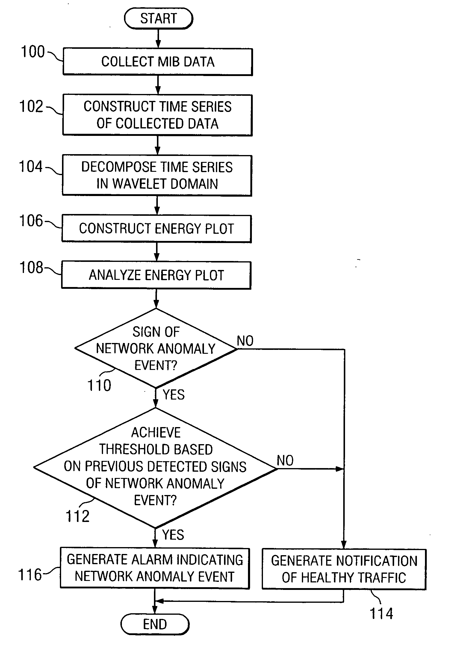
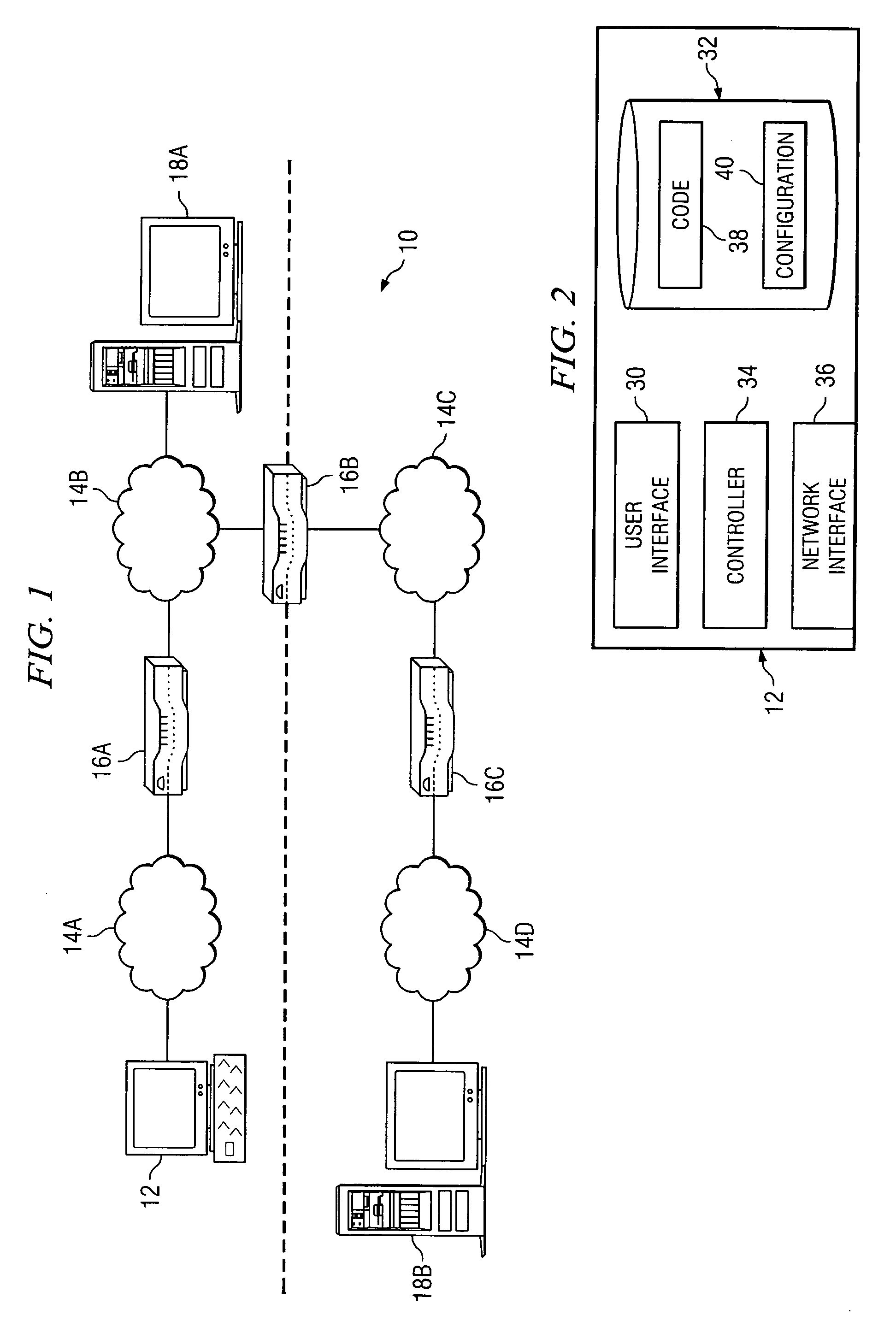
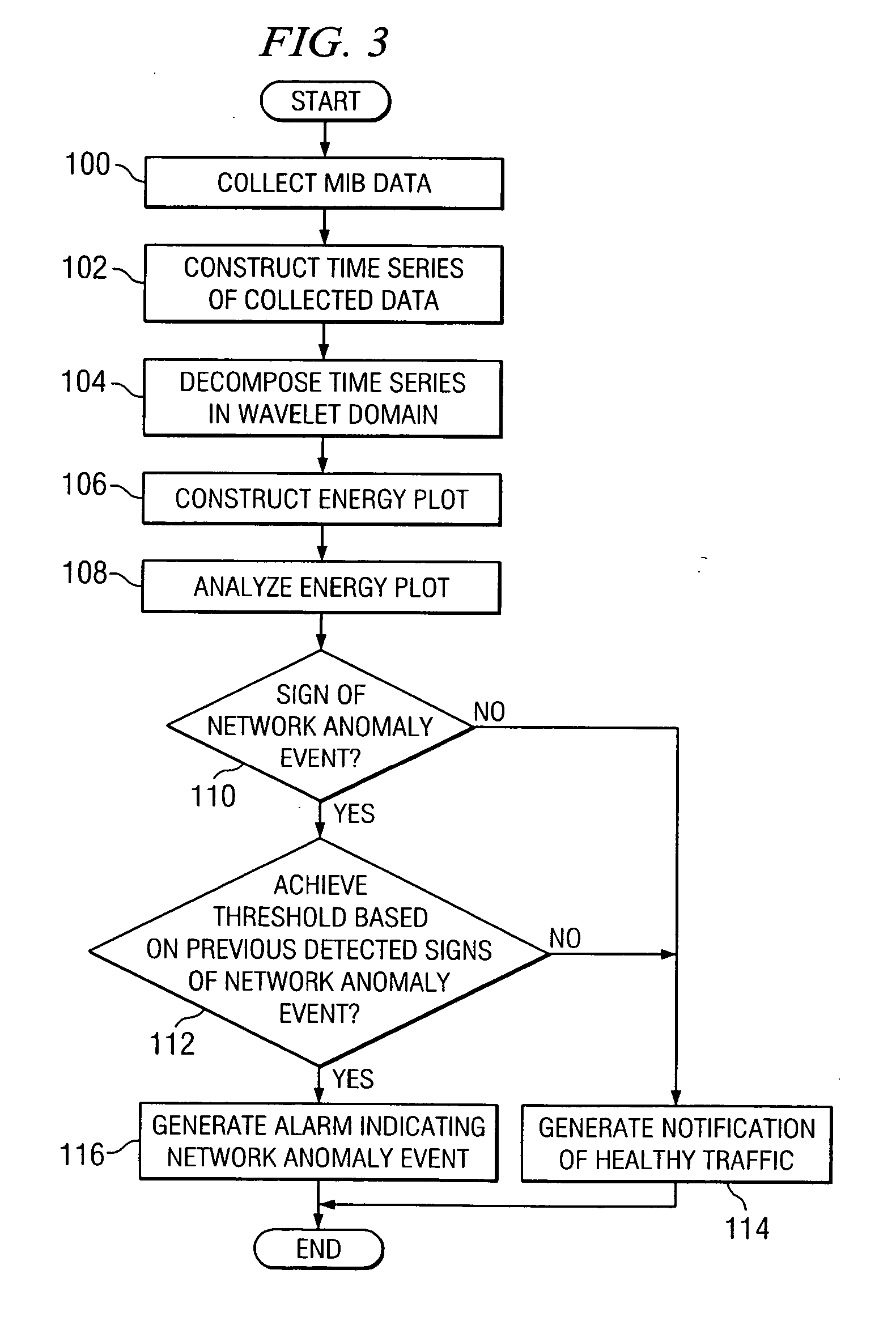
[0013]FIG. 1 illustrates a communication system 10 in accordance with a particular embodiment. Communication system 10 includes an analysis device 12, network segments 14, routers 16 and servers 18 and may comprise any suitable communication networks. Communication system 10 may comprise, for example, networks of major Tier-I providers or national internet service providers or public or private local area networks (LANs) and wide area networks (WANs). In general, analysis device 12 provides analysis of network traffic to diagnose network anomalies, such as misconfigurations, within system 10 that can degrade network performance. More specifically, analysis device 12 may enable detection of misconfigurations and network anomalies between linked devices within communication system 10. According to particular embodiments, analysis device 12 collects traffic data and can detect network anomalies by analyzing characteristics of the collected traffic data. Analysis device 12 can detect a ...


PUM


Abstract

A method for detecting a network anomaly in a network includes collecting management information base (MIB) data from the network at an interval and constructing a time series of the collected data. The method also includes decomposing the time series of the collected data in the wavelet domain, constructing an energy plot based on the time series decomposed in the wavelet domain and analyzing the energy plot to determine a sign of a network anomaly event.

Description

TECHNICAL FIELD OF THE INVENTION [0001] The present invention relates generally to communication networks and, more particularly, to a method and system for detecting a network anomaly in a network. BACKGROUND OF THE INVENTION [0002] Network operators are faced, on a daily basis, with complex network anomalies, particularly misconfigurations, that can seriously undermine the performance of the network infrastructure they operate and diminish revenue. Addressing such anomalies can require the development of effective detection technologies capable of promptly isolating such problems. The range of misconfigurations that appear in wide-scale networks is broad and continues to evolve over time as new protocols and applications are developed. Typically, a specific detection algorithm is designed to identify a well-defined misconfiguration. SUMMARY OF THE INVENTION [0003] The present invention provides a method and system for detecting a network anomaly in a network that substantially eli...

Claims


Application Information

Patent Timeline
Patent Type & Authority Applications(United States)
IPC IPC(8): G06F15/173H04L69/40
CPCH04L41/064H04L63/1458H04L41/0677H04L41/065
Inventor MAGNAGHI, ANTONIOHAMADA, TAKEO
Owner FUJITSU LTD
Why Eureka
Try Eureka