Device and method for processing screw rotor, and cutting tool
- Summary
- Abstract
- Description
- Claims
- Application Information
AI Technical Summary
Benefits of technology
Problems solved by technology
Method used
Image

Examples
first embodiment
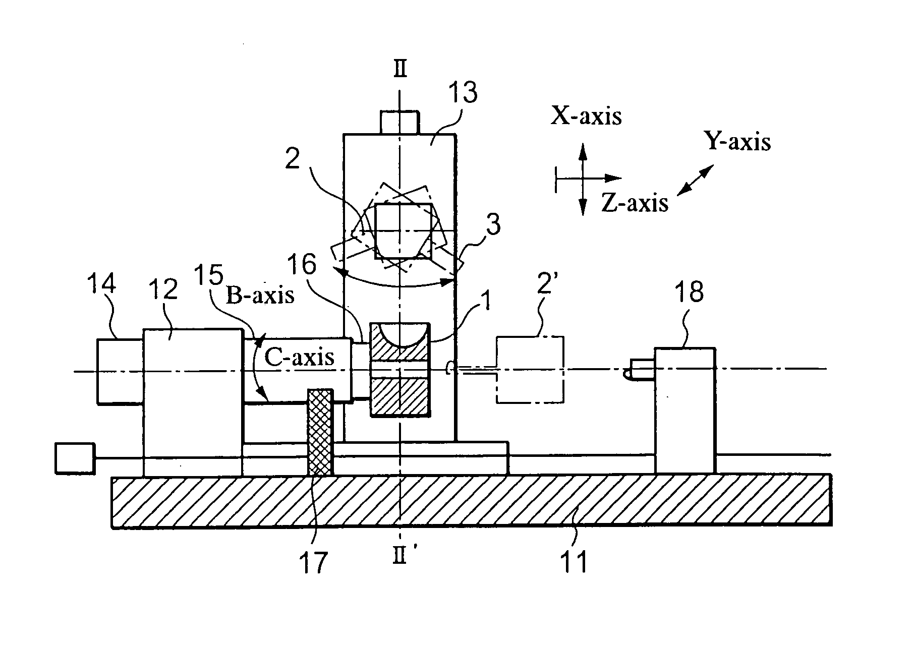
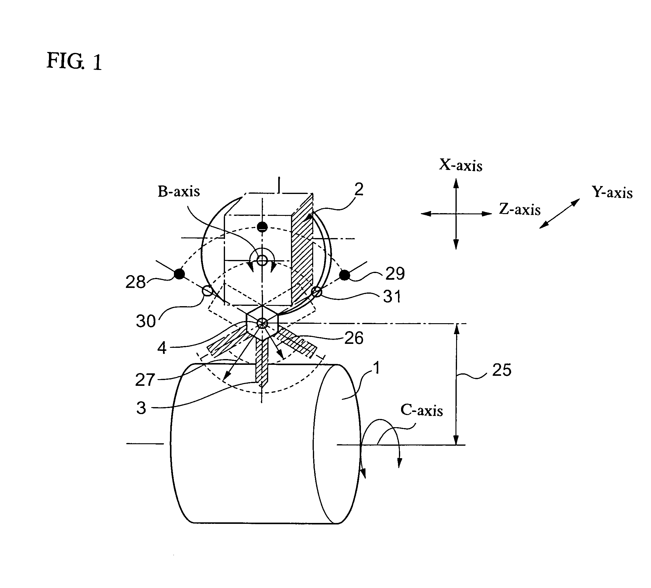
[0040] The principle of a process for manufacturing a screw rotor according to the present invention will now be described by referring to FIG. 1.
[0041] A workpiece 1 as a cylindrical blank for screw cutting rotates around an axis (C-axis) that is a line connecting the center of the top surface (first flat surface) with the center of the bottom surface (second flat surface). A blade holder 2 is disposed at the position orthogonal to the C-axis, namely, above the circumferential surface (outer surface) of the workpiece 1. A tool 3 directing its blade towards the workpiece 1 is disposed at the bottom of the blade holder 2. The blade holder 2 pivots about a B-axis and moves in a Z-axis direction parallel to the C-axis, in an X-axis direction that is a vertical direction, and in a Y-axis direction that is orthogonal to both the Z-axis and the X-axis. In accordance with an NC program, the pivotal movement of the blade holder 2 about the B-axis and the movement of the blade holder 2 alon...
second embodiment
[0072] In the first embodiment, priorities are given to the accuracy of the processing apparatus and processing, and thus the process in a single direction with the groove-side-shaving bit shown in FIG. 9 is described. If a processing apparatus can exhibit the same accuracy in a reciprocating process as that in the single-direction process, the reciprocating process can utilize the time for the tool to return, thereby further reducing the processing time. FIG. 20 shows a groove-side-shaving bit that realizes this reciprocating process.
[0073]FIG. 20 is a perspective view of a reciprocation-type-groove-side-shaving bit 60 inserted into a shaft 25 of the B-axis blade holder. This tool is used for shaving at a cutting feed rate with the shaft 25 fixed. Therefore, a standard-for-oblique-view 61 is provided in order to shift the phase of the tool by 27° with respect to the orientation of the shaft. This tool can be attached to a commercially available tool holder 41 for use.
[0074] The r...
PUM
| Property | Measurement | Unit |
|---|---|---|
| Angle | aaaaa | aaaaa |
| Width | aaaaa | aaaaa |
Abstract
Description
Claims
Application Information
 - Generate Ideas
- Intellectual Property
- Life Sciences
- Materials
- Tech Scout
- Unparalleled Data Quality
- Higher Quality Content
- 60% Fewer Hallucinations
Browse by: Latest US Patents, China's latest patents, Technical Efficacy Thesaurus, Application Domain, Technology Topic, Popular Technical Reports.
© 2025 PatSnap. All rights reserved.Legal|Privacy policy|Modern Slavery Act Transparency Statement|Sitemap|About US| Contact US: help@patsnap.com