Labeler for pipes, conduits, tubes, and rods

Inactive Publication Date: 2006-03-09
THE VOLUSIA HLDG CORP
View PDF38 Cites 26 Cited by
  • Summary
  • Abstract
  • Description
  • Claims
  • Application Information

AI Technical Summary

Benefits of technology

[0011] The present invention overcomes all the previously mentioned problems of labeling. It provides a flat surface for writing. It is not affected by vibration nor is it prone to rotation or lateral slippage. The labeler requires no tools to install. The sign surface can be rigid or fixed in position, or can be adjustable vis-a-vis the pipe being labeled. It can be attached to any piping or conduit, be it free standing or surface mounted. The labeler can be installed in a removable manner as in its basic clip-on use or in a permanent manner sim

Problems solved by technology

The increasing complexity of communication, data, plumbing, gaseous, and electrical systems in use today necessitates the organization and clear labeling of such systems.
Labeling of cables and pipes in the past has included handwriting on the pipe surface, which is problematic in many ways.
Writing on a round or curved surface is difficult, especially if the outside diameter is small, frequently producing a sloppy or illegible result.
The total surface area available for labeling is limited and often not conveniently placed for easy reading.
Repairs or replacement of the underlying pipe or conduit destroys any written information thereon.
This method i

Method used


Image

  • Labeler for pipes, conduits, tubes, and rods
  • Labeler for pipes, conduits, tubes, and rods
  • Labeler for pipes, conduits, tubes, and rods

Examples


first embodiment

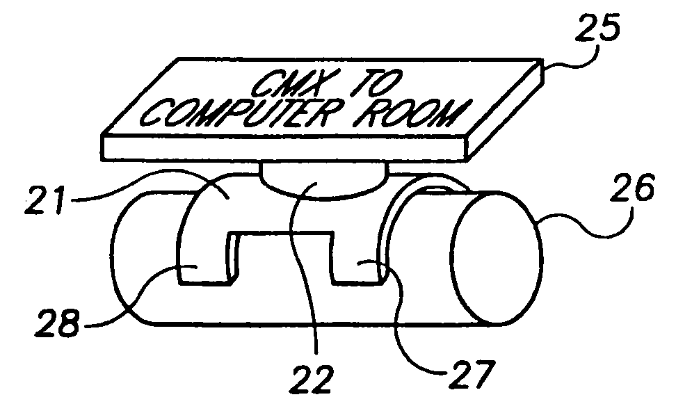
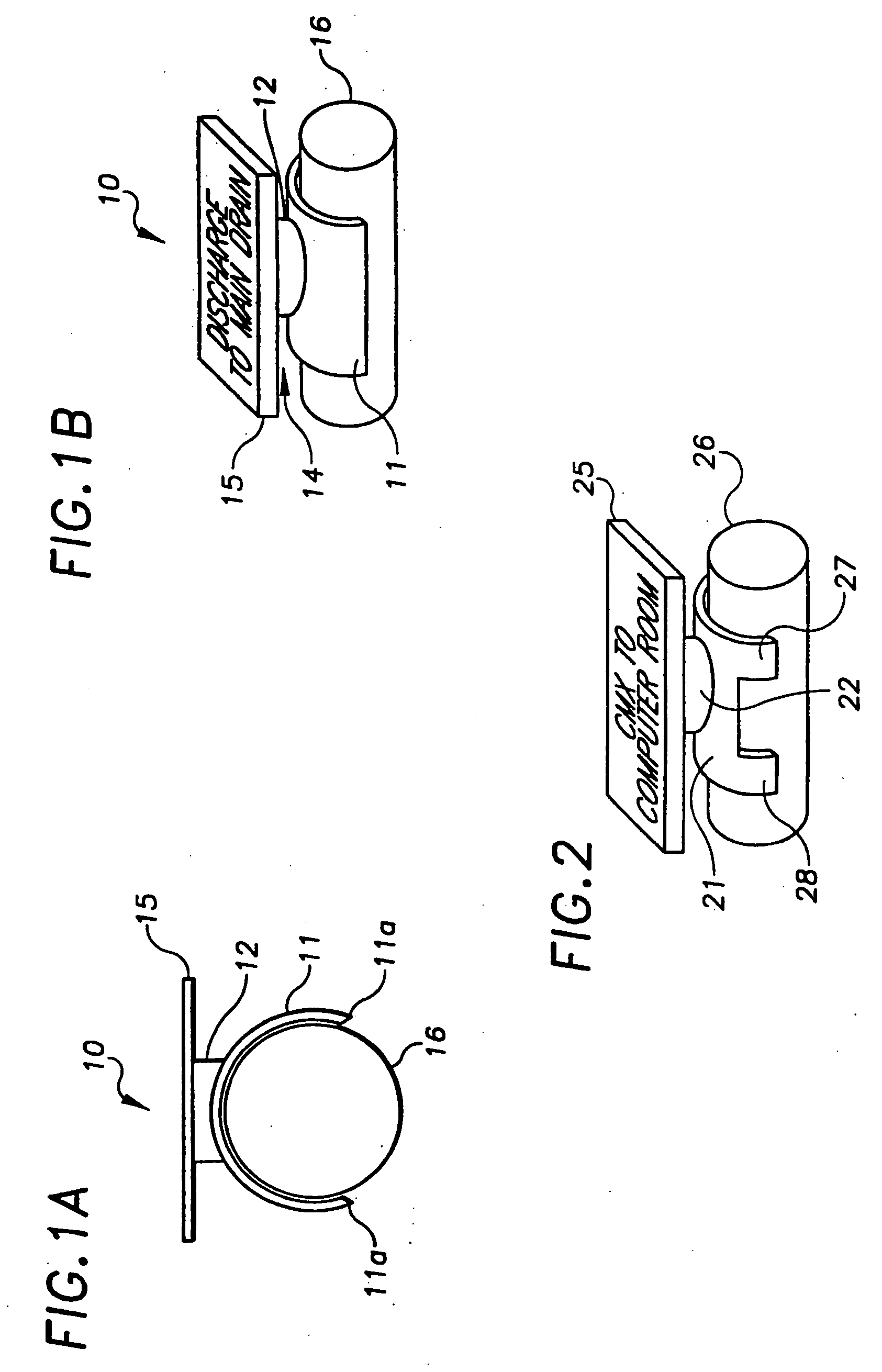
[0037] Referring to FIGS. 1A and 1B, a labeler 10 includes a sign plate 15 permanently molded to a saddle stem 12 which in turn connects to a saddle fitting 11. The inside diameter of saddle fitting 11 is preferably shaped as a section of a circle having a gap of less than 180°, such that when applied to a pipe, tube, or conduit having an outside diameter and an axial length, the inside diameter of the saddle fitting 11 is equal to or slightly smaller than the outside diameter of the pipe, tube or conduit and the inside diameter of the saddle fitting is in contact with the outside diameter of said pipe, tube, or conduit. Sign plate 15 is preferably of a size to allow legible identification of a pipe 16, while being any shape or thickness. Marking of sign plate 15 can be as simple as writing directly on it with a magic marker, or by affixing a computer-produced label, or any other labeling method the user found suitable. For example, the engineers, designers and architects of complex...

second embodiment

[0046] Referring to FIG. 5A, a second embodiment is shown in which a sign plate 55 of a labeler 50 is slightly adjustable. Sign plate 55 connects to a saddle stem 52 via a movable joint 54. A socket portion 53a of joint 54 optionally includes a plurality of slots (not shown) therein to-permit easy connection with a ball portion 53b of joint 54. As with the previously described embodiments, saddle fitting 51 has an inside diameter equal to or slightly smaller than an outside diameter of a pipe 56. Saddle fitting 51 optionally includes one or more saddle legs 57. Joint 54 permits rotation adjustments and slight angling adjustments to be made to sign plate 55.

[0047] Referring to FIG. 5B, a variation of the second embodiment is shown wherein a sign plate 55′ of a labeler 50′ is connected to a saddle fitting 51′ by a ball & knuckle joint 58′ which consists of a knuckle 54′ which fits over a ball 53′. Joint 58′ permits rotation and slight angling adjustments to be made to sign plate 55′. ...

third embodiment

[0048] Referring to FIG. 6, the invention is shown which is adjustable. A labeler 60 includes a saddle fitting 61 permanently molded to a saddle stem 62. Saddle fitting 61 optionally includes saddle legs 67, 68, and an inside diameter of saddle fitting 61 and saddle legs 67, 68 is equal to or slightly smaller than a pipe (not shown). A first movable joint 63A connects a first extension arm 64A to saddle stem 62. A second movable joint 63B optionally connects a second extension arm 64B to first extension arm 64A. A third movable joint 63C optionally connects a sign plate 65 to second extension arm 64B. The basic configuration is sign plate 65 connected to first extension arm 64A, either with or without movable joint 63B. Other variations of extension arms and movable joints are possible. The movable joints shown in the figure are ball and knuckle joints, but any movable joint can be used.

[0049] This embodiment allows for maximum flexibility in positioning sign plate 65. This is of us...


PUM


Abstract

A pipe or conduit labeler includes a saddle leg having an inside diameter equal to or slightly smaller than an outside diameter of a pipe or conduit to be labeled. The saddle leg is molded to a saddle stem which in turn is molded to a sign plate. A user either writes useful information directly on the sign plate or affixes a pre-made label to the plate. The sign plate optionally includes raised lettering or information such as an arrow pre-molded on the plate; or Braille characters. The labeler resiliently clips onto the pipe or conduit being labeled. More complex variations of the labeler include extending arms and moveable joints, enabling the identification of pipes or conduits which are at difficult angles or out of direct sight of a user. The labeler provides a means for quickly and clearly labeling pipes, conduit, tubes, and rods. The labeler can be mass produced as a single mold or in parts with different sign plates of varying size and construction. The sign plate provides a flat surface for writing. The labeler can be temporary, removable, or made permanent simply by applying an adhesive to the saddle portion prior to affixing the labeler.

Description

REFERENCE TO RELATED APPLICATIONS [0001] This application is a continuation-in-part of copending parent patent application Ser. No. 09 / 233,397, filed Jan. 19, 1999, entitled “LABELER FOR PIPES, CONDUITS, TUBES, AND RODS”. The aforementioned application is hereby incorporated herein by reference.FIELD OF THE INVENTION [0002] The invention pertains to the field of identification and marking of wiring, plumbing, and control rods. More particularly, the invention pertains to a device for identifying pipes, conduits, cables, tubes, and rods with information as suits a user. BACKGROUND OF THE INVENTION [0003] The increasing complexity of communication, data, plumbing, gaseous, and electrical systems in use today necessitates the organization and clear labeling of such systems. Examples include communication systems with cables and conduits, laboratory tubing, fire suppression systems supplying a multitude of zones, irrigation systems, swimming pool circulation systems especially those whi...

Claims


Application Information

Patent Timeline
IPC IPC(8): G09F3/00F16L1/00A63B21/055A63B23/03G09F3/20G09F7/02G09F7/16G09F7/18G09F7/20
CPCG09F3/205G09F3/00F16L2201/60
Inventor BOIRE, MARTIN C.BOIRE, JANET L.
Owner THE VOLUSIA HLDG CORP
Why Eureka
Try Eureka