
Structural connector and related assembly method using same

a technology of structural connectors and assembly methods, applied in the direction of rod connections, constructions, fastening means, etc., can solve the problems of increasing material costs to and reducing the service life of the overall manufacturing assembly

Inactive Publication Date: 2006-03-09
W A KRAPF
View PDF4 Cites 12 Cited by
  • Summary
  • Abstract
  • Description
  • Claims
  • Application Information

AI Technical Summary

Benefits of technology

[0004] Therefore, there is a general need in the field of manufacturing assemblies to minimize the weight of assembled structures such as those described above which include the interconnection of at least one pair of box beams, but without sacrificing structural integrity.
[0006] Therefore and according to a preferred aspect of the present invention, there is described a connector for mating at least two structural components, said connector being matingly fitted into a tubular end of a first structural component wherein said connector includes at least one flexible cantilevered ear portions, said at least one cantilevered ear portion having a protrusion for engaging a lateral opening of the tubular end of the first structural component when said connector is attached thereto, thereby securing said connector.
[0007] Once seated, the connector permits the engagement of at least one fastener, thereby permitting the attachment of a second structural component to the first structural component. The connector is seated within the open end of the tubular structural component wherein the second component can be assembled to the end containing the connector. Additionally, securing the at least one fastener to the connector also prevents the connector from being removed from the at least one structural component in that the fastener is mounted into the open region or gap that permits flexion of the cantilevered ear portions.
[0015] An advantage realigned by the present invention is that an effective manufacturing method is realized that does not impact the structural design of an assembly, but which can influence the overall weight and cost thereof.

Problems solved by technology

The addition of these interior bosses, however, provide additional weight to the beams as well as increased material costs to the overall manufacturing assembly.
Removal of the bosses in the center of the beam; that is, the axial portion of the box beam that does not require the use of fasteners would obviously ease some of the above concerns, but performing such removal would be extremely difficult, costly and time consuming.

Method used


Image

  • Structural connector and related assembly method using same
  • Structural connector and related assembly method using same
  • Structural connector and related assembly method using same

Examples


Embodiment Construction

[0025] The following description relates to a pair of embodiments of a structural connector as described for use with a specific manufacturing assembly. It will be readily apparent, however, from the discussion that follows that other suitable connector designs can be imagined using the inventive concepts described herein and that a number of suitable uses other than the specific manufacturing assembly depicted will be available by those of ordinary skill in the field. In addition, certain terms are used throughout the present discussion in order to provide a suitable frame of reference with regard to the accompanying drawings, such as “top”, “bottom”, “lateral”, “square”, “longitudinal”, “end” and the like. It is not intended, however, except where specifically indicated otherwise, that these terms are intended to be restrictive of the scope of the present invention.

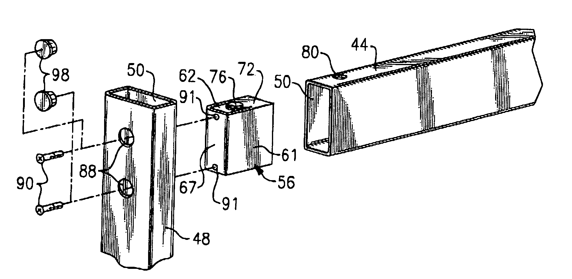
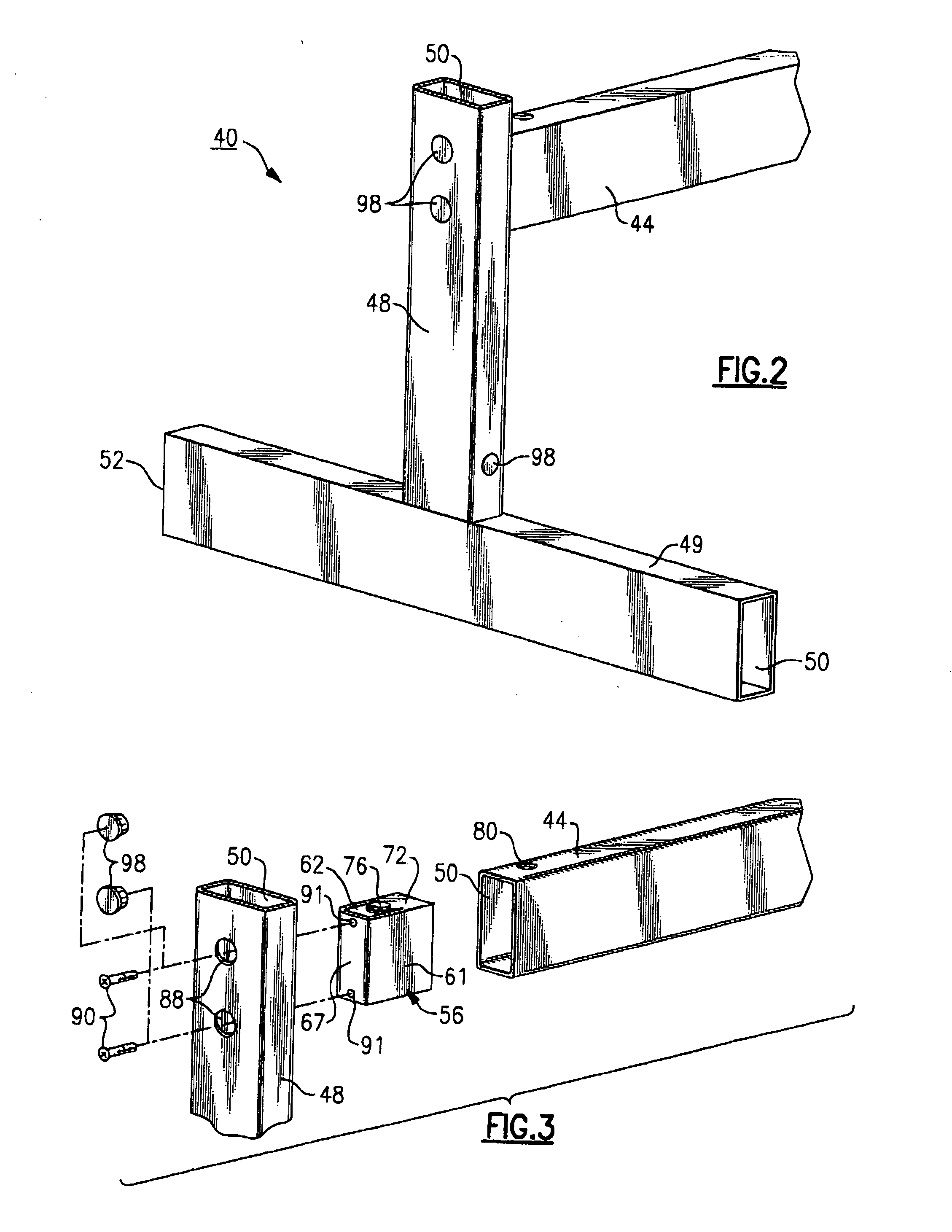
[0026] Referring to FIG. 2, there is shown a portion of a manufacturing assembly 40 that includes a number of inters...


PUM


Abstract

A structural connector for a manufacturing assembly includes a body portion sized to be substantially fitted into an open end of a first hollow structural component of a manufacturing assembly. The structural connector includes at least one flexible cantilevered ear portion which is sized to engage with a corresponding lateral opening provided in the first hollow structural component. Once seated, the connector accepts at least one fastener extending laterally through a second structural component which is fitted orthogonally, relative to the open end of the first structural component, permitting interconnection between the second structural component and the first structural component.

Description

FIELD OF THE INVENTION [0001] This invention relates to the field of manufacturing assemblies and in particular to a structural connector used in manufacturing assemblies defined by at least two or more structural hollow structural members, such as box beams, and a preferred method of assembly using at least one said structural connector. BACKGROUND OF THE INVENTION [0002] There are a variety of known manufacturing assemblies, such as those for free standing displays, scheduling boards, easels, and the like, that comprise a frame that requires the interconnection of at least two box beams in which some of the beams form joints with one another. Quite often, these beam members are made from an extruded aluminum or other lightweight material in order to provide sufficient strength and rigidity to the overall structure. The beams are essentially hollow and require the use of fasteners when mating the beams together, particularly those beams that interconnect with one another in the for...

Claims


Application Information

Patent Timeline
IPC IPC(8): E04C2/38
CPCF16B7/0446F16B37/043F16B7/18
Inventor KRAPF, WALLACE A.ROSSBOROUGH, DANIEL W.
Owner W A KRAPF
Learn More